Assembly / Schematic Layouts
www.ti.com
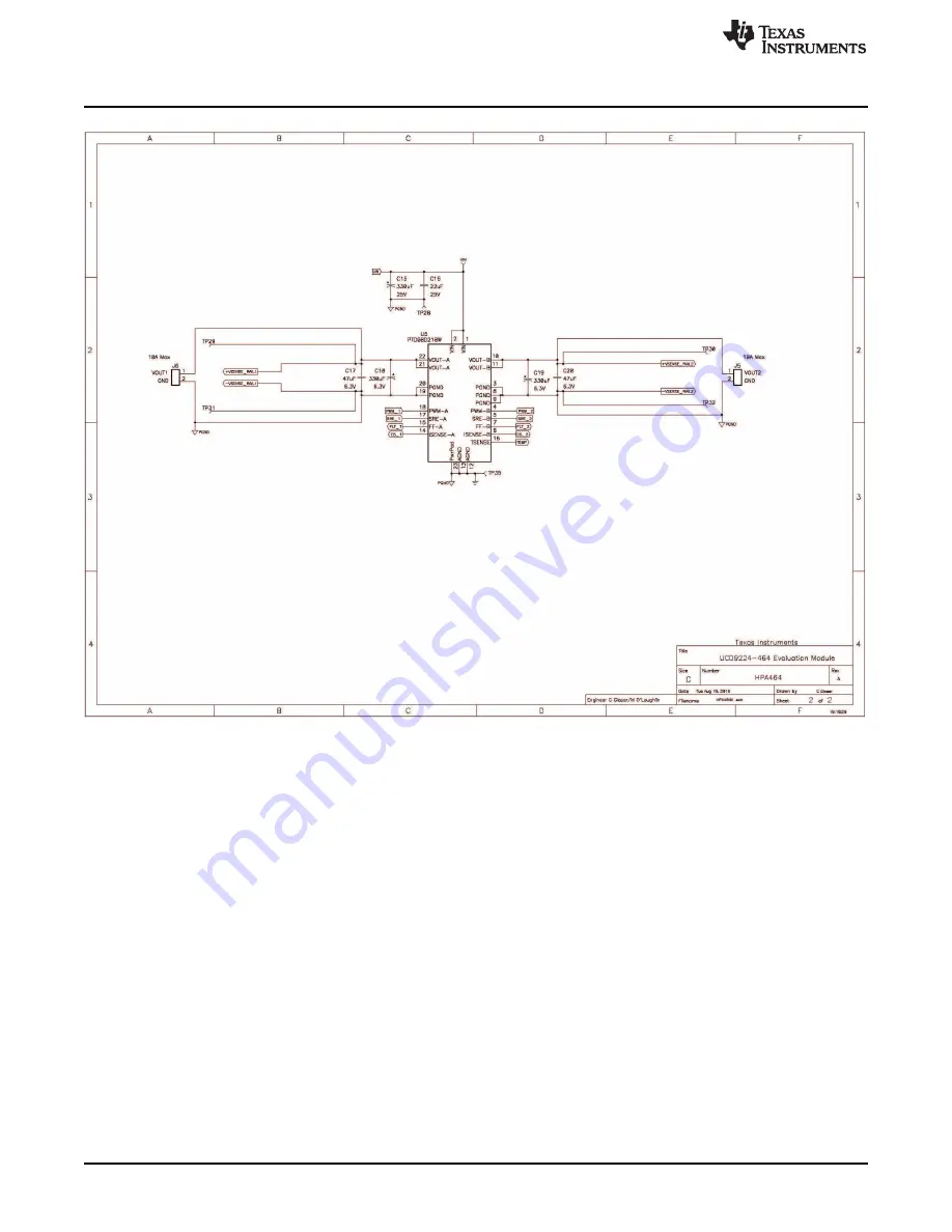
Figure 3. Schematic 2
8
UCD9224EVM-464 Digitally Controlled Dual-Rail POL
SLUU443 – March 2011
Submit Documentation Feedback
© 2011, Texas Instruments Incorporated
Page 1: ...Using the UCD9224EVM 464 User s Guide Literature Number SLUU443 March 2011 ...
Page 2: ...UT1 and 1 2 V VOUT2 without user intervention once the input voltage has reached the power system s under voltage lockout that is set within the controller The PMBus compatible serial data interface included on the EVM allows the user to connect the power system to a Windows based host computer running the Fusion Digital Power Designer software with the USB Interface Adapter EVM refer to the Secti...
Page 3: ...ocks Between Multiple UCD92xx Devices 12 Bit Digital Monitoring of Power Supply Parameters Including Input Output Current and Voltage Temperature at Each Power Stage Multiple Levels of Over current Fault Protection External Current Fault Inputs Analog Comparators Monitor Current Sense Voltage Current Continually Digitally Monitored Over and Under voltage Fault Protection Over temperature Fault Pro...
Page 4: ...de Input Voltage Range of 4 75 V to 18 V operation to 2 2 V with external VGG bias voltage Up to 10 A Output Current Per Channel Operational to 2 MHz Switching Frequency High Side Current Limit With Current Limit Flag Onboard Regulated 6 V Driver Supply From VIN Thermal Protection Temperature Sense Output Voltage Proportional to Chip Temperature UVLO and OVLO Circuits Ensure Proper Drive Voltage R...
Page 5: ...OUT1 10 A 2 450 2 5 2 550 V Output load current IOUT1 10 Output voltage regulation Line regulation VIN 10 8 V to 13 2 V IOUT1 10 A 1 0 Load regulation IOUT1 10 to 100 VIN 12 V 1 0 Output voltage ripple IOUT1 10 A 30 mVpp Output over current 12 5 A Output voltage VOUT2 Output current 10 A 1 750 1 8 1 850 V Output load current IOUT2 10 A Output voltage regulation Line regulation VIN 10 8 V to 13 2 V...
Page 6: ...ematic Layouts www ti com 4 Assembly Schematic Layouts Figure 1 Top Assembly 6 UCD9224EVM 464 Digitally Controlled Dual Rail POL SLUU443 March 2011 Submit Documentation Feedback 2011 Texas Instruments Incorporated ...
Page 7: ...www ti com Assembly Schematic Layouts Figure 2 Schematic 1 7 SLUU443 March 2011 UCD9224EVM 464 Digitally Controlled Dual Rail POL Submit Documentation Feedback 2011 Texas Instruments Incorporated ...
Page 8: ...Assembly Schematic Layouts www ti com Figure 3 Schematic 2 8 UCD9224EVM 464 Digitally Controlled Dual Rail POL SLUU443 March 2011 Submit Documentation Feedback 2011 Texas Instruments Incorporated ...
Page 9: ...ed Wire Gauge Input Voltage 20 AWG min Output Load 16 AWG min 5 1 1 Test configuration Monitoring and Control Functionality PC computer running Microsoft OS version XP 32 bit Vista 32 bit Vista 64 bit untested should be compatible 7 32 or 64 bit Texas Instruments USB Interface Adapter EVM P N USB to GPIO User s Guide SLLU093 Fusion Digital Power Designer Software Installer Executable File fusion_d...
Page 10: ...i com 5 2 Recommended Test Setup Figure 4 UCD9224EVM 464 Recommended Test Set Up 10 UCD9224EVM 464 Digitally Controlled Dual Rail POL SLUU443 March 2011 Submit Documentation Feedback 2011 Texas Instruments Incorporated ...
Page 11: ...K Input reference for external voltage tracking J4 2 Jan ADDR 1 Jumper location to modify ADDR 1 setting 4 Mar ADDR 0 Jumper location to modify ADDR 0 setting J5 1 VOUT2 Output voltage 2 2 VOUT2 Output voltage 2 return J6 1 VOUT1 Output voltage 1 2 VOUT1 Output voltage 1 return J7 optional 1 REG 3 3 V from onboard regulator U1 1 2 3 3 V 3 3 V supply for UCD9224 controller 1 3 EXT 3 3 V from J2 5 P...
Page 12: ...urrent sense input and input to analog comparator 2 TP1 AGND Analog ground reference TP2 AGND Analog ground reference TP3 nRESET Reset pin active low TP4 V33FB Base drive control for 3 3 V linear regulator transistor no connect if using an external 3 3 V LDO regulator TP5 SEQ 1 Sequencing input output GPIO TP6 CS 1B Power stage 1B current sense input TP7 nTRST JTAG test reset pull down to ground u...
Page 13: ...t configuration that will allow the user to immediately power up the EVM and begin testing as either a stand alone power solution or as a networked power system when accessing the PMBus interface 7 1 Test Setup 1 Set the external input power supply s output voltage to 12 V 0 5 V and current limit the supply at 5 0 A Ensure the output voltage is disabled 2 Attach supply connection leads AWG 20 mini...
Page 14: ...input supply to 12 0 V confirm operation is still disabled 6 Disable the external input voltage source 7 4 Turn On Timing Power Good Testing the currently configured settings for Turn On Timing and Power Good 1 Attach Channel 1 of the oscilloscope between VOUT1 and PGND test points and Channel 2 between VOUT2 and PGND test points 2 Set the oscilloscope to 1 0 V div vertical scale on both channels ...
Page 15: ...he application icon in the program folder through the Windows Start Menu default location Start All Programs Texas Instruments Fusion Digital Power Designer Fusion Digital Power Designer NOTE The Offline Mode version of the GUI is for project file development only and will not be able to access an operating power system 3 The GUI will scan the bus for available devices and after this discovery pro...
Page 16: ...earlier section of the plot This reflects the application of margining to the output voltage with the Margin High setting still visible at the bottom of the column just to the left of the plots Figure 7 Fusion Digital Power Designer Software Monitor Page Rail 1 NOTE A Low VIN alert may be present when monitoring is first accessed but it does not affect the operation of the system This is a typical...
Page 17: ...ssue and possibly initiated a response then the faults can be cleared Return the OT Warn level to 85 C and click the Clear Faults button Now change the OT Fault level to 20 C and click the Write button observe that several items changed state within the Status Registers Lines section The Temp Status and Logged Faults both indicate OT Fault Misc Status indicates POWER_GOOD and the SMBALERT is Asser...
Page 18: ... Next button and the Select Project Items to Import window will open set the check boxes as shown in Figure 8 and click the Next button In the Review Parameters to Import window click the Select All button and then click the Write Checked button The Fusion GUI will download the default configuration settings it may generate two warnings about NACK of SYNC_OFFSET command this is OK the controller N...
Page 19: ...90 8 www ti com Performance Data and Typical Characteristic Curves 8 Performance Data and Typical Characteristic Curves Figure 9 through Figure 12 present typical performance curves for UCD9224EVM 464 8 1 Efficiency Figure 9 2 5 V Efficiency 1 2 V no load 8 2 Output Ripple Figure 10 1 2 V Efficiency 2 5 V no load 19 SLUU443 March 2011 UCD9224EVM 464 Digitally Controlled Dual Rail POL Submit Docume...
Page 20: ...Characteristic Curves www ti com Figure 11 2 5 V Output Ripple Figure 12 1 2 V Output Ripple 20 UCD9224EVM 464 Digitally Controlled Dual Rail POL SLUU443 March 2011 Submit Documentation Feedback 2011 Texas Instruments Incorporated ...
Page 21: ... following figures Figure 13 through Figure 17 show the design of the UCD9224EVM 464 printed circuit board Figure 13 Top Layer Assembly Drawing top view 21 SLUU443 March 2011 UCD9224EVM 464 Digitally Controlled Dual Rail POL Submit Documentation Feedback 2011 Texas Instruments Incorporated ...
Page 22: ...sembly Drawing and PCB layout www ti com Figure 14 Top Copper top view 22 UCD9224EVM 464 Digitally Controlled Dual Rail POL SLUU443 March 2011 Submit Documentation Feedback 2011 Texas Instruments Incorporated ...
Page 23: ...m EVM Assembly Drawing and PCB layout Figure 15 Internal Layer 1 top view 23 SLUU443 March 2011 UCD9224EVM 464 Digitally Controlled Dual Rail POL Submit Documentation Feedback 2011 Texas Instruments Incorporated ...
Page 24: ...bly Drawing and PCB layout www ti com Figure 16 Internal Layer 2 top view 24 UCD9224EVM 464 Digitally Controlled Dual Rail POL SLUU443 March 2011 Submit Documentation Feedback 2011 Texas Instruments Incorporated ...
Page 25: ...m EVM Assembly Drawing and PCB layout Figure 17 Bottom Copper bottom view 25 SLUU443 March 2011 UCD9224EVM 464 Digitally Controlled Dual Rail POL Submit Documentation Feedback 2011 Texas Instruments Incorporated ...
Page 26: ...1 R1 Resistor 0 001 Ω 1 2 W 1 2010 SMD Vishay Dale VA WSL20101L000FEA 4 R14 R15 Resistor 100 kΩ OHM 1 10 W 1 0603 SMD Vishay Dale VA CRCW0603100KFKEA R16 R19 2 R17 R18 Resistor 20 0 kΩ 1 10 W 1 0603 SMD Vishay Dale VA CRCW060320K0FKEA 8 R2 R3 Resistor 10 0 kΩ 1 10 W 1 0603 SMD Vishay Dale VA CRCW060310K0FKEA R5 R7 R8 R11 R12 R20 2 R21 R23 Resistor 76 8 kΩ 1 10 W 1 0603 SMD Panasonic ECG VA ERJ 3EK...
Page 27: ...uct This notice contains important safety information about temperatures and voltages For additional information on TI s environmental and or safety programs please contact the TI application engineer or visit www ti com esh No license is granted under any patent right or other intellectual property right of TI covering or relating to any machine process or combination in which such TI products or...
Page 28: ...horized for use in safety critical applications such as life support where a failure of the TI product would reasonably be expected to cause severe personal injury or death unless officers of the parties have executed an agreement specifically governing such use Buyers represent that they have all necessary expertise in the safety and regulatory ramifications of their applications and acknowledge ...
Page 29: ...Mouser Electronics Authorized Distributor Click to View Pricing Inventory Delivery Lifecycle Information Texas Instruments UCD9224EVM 464 ...