


USB2ANY
TPS929120EVM
x
x
x
x
x
VSUPPLY_EXT
USB
cable
TPS929120CANEVM
GND
DB09 cable
TP1
TP2
J3
J4
J7
DC
Supply
12V
+
-
How to Get Started
5
SLVUBM2B – April 2019 – Revised December 2019
Copyright © 2019, Texas Instruments Incorporated
TPS929120EVM User's Guide
Table 1. TPS929120EVM Jumpers Setting without TPS929120CANEVM Connected
HEADER
SETTING
J2, J4, J5, J6, J10, J17, J19, J20, J40
Open
J8, J9, J11
Short
J12
Short “FS” to “H”
J13
Short “ADDR2” to “L”
J14
Short “ADDR1” to “L”
J15
Short “ADDR0” to “H”
J16
Short “TX_C” to “RX”, “RX_C” to “TX”, “ERR_C” to “ERR”,
“ADDR2/CLK_C” to “ADDR2/CLK”, “ADDR1/CLK_C” to
“ADDR1/CLK”, “ADDR0/CLK_C” to “ADDR0/CLK”
J30
Short “OUTx” to “OUTx_MONO”, where x=0 to 11
All headers paralleled with LEDs
Open
3.1.2
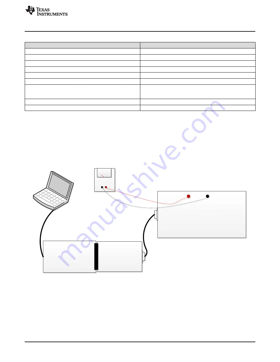
Communication with CAN Transceiver
shows the hardware setup when TPS929120CANEVM is used.
shows the jumper
configurations for TPS929120EVM with TPS929120CANEVM connected. With this setup, the clock and
PWM signal terminals from the USB2ANY are disconnected to such signal terminals of the TPS929120-
Q1 device on the TPS929120EVM. As a result, an extra instrument for generating the PWM or clock
signal is required to simulate the external PWM or clock input to TPS929120EVM, because both signal
outputs from USD2ANY board are not transmitted to TPS929120EVM if TPS929120CANEVM is
connected.
Figure 4. Hardware Setup with CAN Transceiver
•
Connect a 12-V power supply to TP1 (VSUPPLY_EXT) and TP1 (GND).
•
Connect USB2ANY tool to PC through USB cable.
•
Plug TPS929120CANEVM to USB2ANY tool through the J3 header of TPS929120CANEVM.
•
Connect TPS929120CANEVM to TPS929120EVM through the J4 connector of TPS929120CANEVM
and the J7 connector of TPS929120EVM with DB-09 cable.


