Texas Instruments TPS65400 User Manual Download Page 5

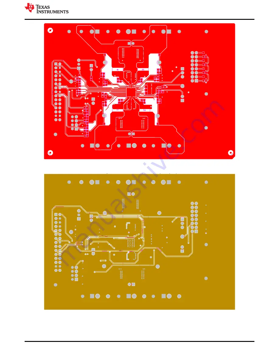
Figure 3-2. Board Layout (Top Layer)

Figure 3-3. Board Layout (Second Layer)

www.ti.com

Board Layout

SLVUAC4A – OCTOBER 2014 – REVISED MAY 2021

Submit Document Feedback

TPS65400 Buck Converter Evaluation Module User's Guide

5

Copyright © 2021 Texas Instruments Incorporated

Summary of Contents for TPS65400

Page 1: ...Third Layer 6 Figure 3 5 Board Layout Bottom Layer 6 Figure 4 1 Headers Description and Jumper Placement 7 Figure 4 2 USB Interface Adapter Quick Connection Diagram 9 Figure 4 3 Connect to TPS65400 EV...

Page 2: ...he individual enable pins or by programming the sequence through the I2C bus into the onboard EEPROM Output voltages can be set through external resistor networks and VREF can be programmed from 0 6 t...

Page 3: ...C36 GND 2 2uH L4 VOUT4 GND GND VDDD 1 2 3 4 5 6 7 8 9 10 11 12 13 14 15 16 J10 VDDA VDDA J14 J15 J2 J5 J7 J9 SH JP3 SH JP4 SH JP5 SH JP6 VDDD SS1 VDDD VDDD VDDD GND SS2 SS3 SS4 VDDA PGOOD RCLOCK_SYNC...

Page 4: ...nted circuit board PCB layouts Figure 3 1 Component Placement Top Layer Board Layout www ti com 4 TPS65400 Buck Converter Evaluation Module User s Guide SLVUAC4A OCTOBER 2014 REVISED MAY 2021 Submit D...

Page 5: ...er Figure 3 3 Board Layout Second Layer www ti com Board Layout SLVUAC4A OCTOBER 2014 REVISED MAY 2021 Submit Document Feedback TPS65400 Buck Converter Evaluation Module User s Guide 5 Copyright 2021...

Page 6: ...yer Figure 3 5 Board Layout Bottom Layer Board Layout www ti com 6 TPS65400 Buck Converter Evaluation Module User s Guide SLVUAC4A OCTOBER 2014 REVISED MAY 2021 Submit Document Feedback Copyright 2021...

Page 7: ...M Figure 4 1 Headers Description and Jumper Placement Test points 1 LX of VOUT1 2 LX of VOUT2 3 LX of VOUT3 4 LX of VOUT4 VOUT1 VOUT2 VOUT3 VOUT4 www ti com Bench Test Setup Conditions SLVUAC4A OCTOBE...

Page 8: ...rosoft Windows 2000 Windows XP or Windows 7 operating system USB port Minimum of 30MB of free hard disk space 100MB recommended Minimum of 256MB of RAM 4 3 Hardware Setup After connecting the power su...

Page 9: ...ox If an incorrect firmware version is installed the software automatically searches on the Internet if connected for updates If a new update is available the software notifies the user of the update...

Page 10: ...el to connect with the EVM board 1 Click on Rescan Slaves 2 Click on LM26430 00F1 6a 3 Click the No button on the popup dialog Figure 4 3 Connect to TPS65400 EVM with EVM GUI 4 Click on PMBus Register...

Page 11: ...e 4 5 Global Commands Figure 4 6 Status and Main Setting Panel www ti com Bench Test Setup Conditions SLVUAC4A OCTOBER 2014 REVISED MAY 2021 Submit Document Feedback TPS65400 Buck Converter Evaluation...

Page 12: ...option is to Apply Changes Immediately if this checkbox is selected any change is immediately sent to the EVM STORE_DEFAULT_ALL must be clicked to write all settings to EEPROM EEPROM values can be re...

Page 13: ...9 Vref Ramping Up and Down Panel www ti com Bench Test Setup Conditions SLVUAC4A OCTOBER 2014 REVISED MAY 2021 Submit Document Feedback TPS65400 Buck Converter Evaluation Module User s Guide 13 Copyr...

Page 14: ...ort from USB2ANY to the USB port on the host computer 2 Apply 12 V to J6 3 Open the GUI on computer Power Up Procedure www ti com 14 TPS65400 Buck Converter Evaluation Module User s Guide SLVUAC4A OCT...

Page 15: ...2 Remove or shutdown 12 V on J6 3 Remove USB2ANY www ti com Power Down Procedure SLVUAC4A OCTOBER 2014 REVISED MAY 2021 Submit Document Feedback TPS65400 Buck Converter Evaluation Module User s Guide...

Page 16: ...1 0 1 F CAP CERM 0 1 F 50 V 10 X7R 0603 603 06035C104KAT2A AVX C40 C42 C43 C44 4 4700 pF CAP CERM 4700 pF 100 V 10 X7R 0603 603 06031C472KAT2A AVX C45 1 100 pF CAP CERM 100 pF 25 V 10 X7R 0603 603 060...

Page 17: ...3 R34 R36 R37 6 1 0k RES 1 0 k 5 0 1 W 0603 603 CRCW06031K00JNEA Vishay Dale R29 R30 2 3 0k RES 3 0 k 5 0 1 W 0603 603 CRCW06033K00JNEA Vishay Dale R35 1 374k RES 374 k 1 0 1 W 0603 603 CRCW0603374KFK...

Page 18: ...to Revision A May 2021 Page Updated user s guide title 2 Updated the numbering format for tables figures and cross references throughout the document 2 Revision History www ti com 18 TPS65400 Buck Con...

Page 19: ...ther than TI b the nonconformity resulted from User s design specifications or instructions for such EVMs or improper system design or c User has not paid on time Testing and other quality control tec...

Page 20: ...These limits are designed to provide reasonable protection against harmful interference in a residential installation This equipment generates uses and can radiate radio frequency energy and if not in...

Page 21: ...instructions set forth by Radio Law of Japan which includes but is not limited to the instructions below with respect to EVMs which for the avoidance of doubt are stated strictly for convenience and s...

Page 22: ...any interfaces electronic and or mechanical between the EVM and any human body are designed with suitable isolation and means to safely limit accessible leakage currents to minimize the risk of electr...

Page 23: ...R DAMAGES ARE CLAIMED THE EXISTENCE OF MORE THAN ONE CLAIM SHALL NOT ENLARGE OR EXTEND THIS LIMIT 9 Return Policy Except as otherwise provided TI does not offer any refunds returns or exchanges Furthe...

Page 24: ...are subject to change without notice TI grants you permission to use these resources only for development of an application that uses the TI products described in the resource Other reproduction and...

Reviews: