2 Configurations and Modifications
These evaluation modules are designed to provide access to the features of the TPS543620. The U2 design
provides jumpers for testing different configurations. Jumper selections must be made prior to enabling the
TPS543620.
If a desired configuration is not available, some modifications can be made to this module. When modifications
are made to the components on the EVM, the internal compensation option selected with the MODE pin resistor
can need to be changed. Changes to the f
SW
, output voltage, output inductor, and output capacitors can require
a change in the compensation. TPS543620 data sheet equations or WEBENCH can be used to calculate the
output capacitor value, compensation, f
SW
, and inductance. Ensure all components have sufficient voltage and
current ratings.
2.1 Output Voltage
In the U1 design, the output voltage is set by the resistor divider network of R7 (R
FBT
) and R8 (R
FBB
). R8 is
fixed at 1.00 kΩ to set the FB divider current at approximately 500 µA. To change the output voltage of the EVM,
the value of resistor R7 must change. Changing the value of R7 can change the output voltage above the 0.5-V
reference voltage (V
REF
). The value of R7 for a specific output voltage can be calculated using
. After
changing R7, the feedfoward capacitor (C8) can also need to be changed.
OUT
FBT
FBB
REF
V
R
R
1
V
§
·
u ¨
¸
©
¹
(1)
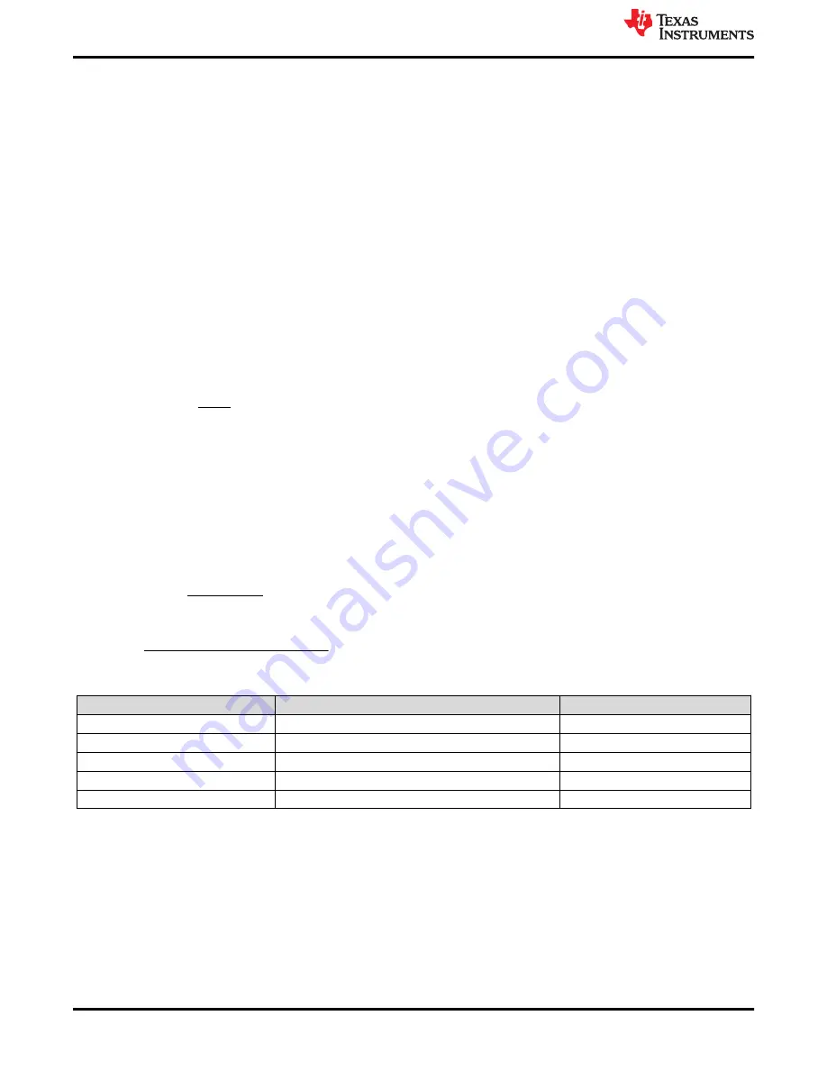
In the U2 design, there are a few ways to set the output voltage. First, jumper J14 can be used to select between
the options shown in
. If the desired output voltage is not available, a resistor must be changed. For
output voltages less than 0.8 V, TI recommends leaving J14 open and increasing R21. R21 becomes R
FBB
and
the required value for can be calculated with
, where R
FBT
is R15. For output voltages greater than
0.8 V, the jumper output voltage options can be changed by changing one of the resistors R23-R26. The R
FBJ
resistor value to get a desired equivalent R
FBB
resistance can be calculated with
. To use J14 for
output voltages 3.3 V or larger, R20 should be reduced to 499 Ω.
REF
FBB
FBT
OUT
REF
V
R
R
V
V
u
(2)
FBB
FBJ
FBB
R
R20
R21
R20
R21
R
R21
R
u
u
(3)
Table 2-1. VOUT Selection
JUMPER SETTING
EQUIVALENT BOTTOM FB RESISTOR (R
FBB
)
NOMINAL OUTPUT VOLTAGE
Open
R21 = 8.25 kΩ
0.803 V
(R23+R20)||R21 = 4.97 kΩ
1.003 V
3 to 4 pin shorted
(R24+R20)||R21 = 3.55 kΩ
1.204 V
5 to 6 pin shorted
(R25+R20)||R21 = 2.48 kΩ
1.507 V
7 to 8 pin shorted
(R26+R20)||R21 = 1.92 kΩ
1.803 V
(1)
Default Setting
Configurations and Modifications
6
TPS543620 SWIFT™ Step-Down Converter Evaluation Module User's Guide
SLVUBQ1A – AUGUST 2020 – REVISED MAY 2021
Copyright © 2021 Texas Instruments Incorporated


