


4 TPS23882B1 GUI Setup
4.1 TPS23882B1 GUI Installation
TI's TPS23882B1 GUI is used with the TPS23882B1 to control the port and provide real-time feedback on port
telemetry. Download the TPS23882B1 GUI from the
TPS23882B1 product folder page
Tools and software
section.
Follow the onscreen instructions to complete the installation. The TPS23882B1 GUI uses the USB2ANY as
an interface between the PC USB port and the BOOST-PSEMTHR8-097 J2 connector (I2C interface). Before
starting the TPS23882B1 GUI, make sure the USB2ANY is properly connected to TPS23882B1 and the EVM is
supplied with a 44- to 57-V power supply as shown in
.
4.2 TPS23882B1GUI Operation
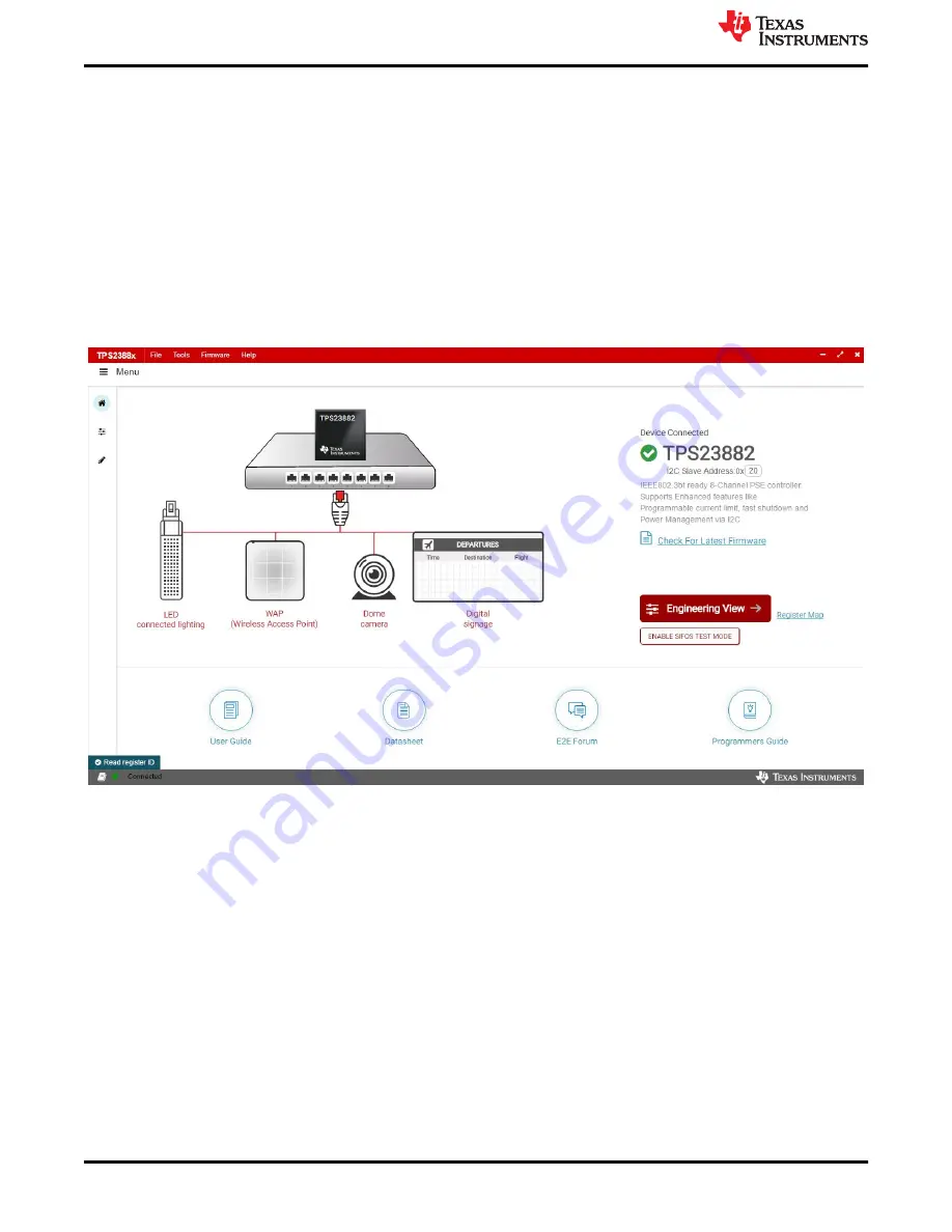
Start the TPS23882B1 GUI by double clicking the GUI icon. A window similar to
will come up.
Figure 4-1. TPS23882B1 GUI Startup Window
The default device address in the GUI is set to 0x20 which matches the default configuration of the EVM (J4 on
the daughter card is installed with jumpers). The GUI sets the TPS23882B1 in configuration B mode (see the
GENERAL MASK Register
section of the data sheet for details). The address can be programed through the
A1 to A4 pins and the I2C address setting in the GUI needs to match the hardware configuration. See the
Pin
Status Register
section of the data sheet for details. The startup page contains links to the EVM user's guide,
TPS23882B1 data sheet, E2E forum and MSP430 reference code. Four popular PD end-equipment images are
connected to the PSE switch. Links to the recommended PD device for each end equipment are also provided.
Once the TPS23882B1 device is connected, click Firmware to select firmware to be loaded to TPS23882B1.
TPS23882B1 GUI Setup
10
TPS23882B1EVM: PoE, PSE, TPS23882B1
Evaluation Module
SLVUC36 – APRIL 2021
Copyright © 2021 Texas Instruments Incorporated