


-
m
m
t
25
s
HEX =
22
s
Setup
2.3.3
Operation in Advanced SPI Mode
The advanced SPI mode has additional features to the default SPI mode. A control byte is written to the
SDI and shifted with the MSB first. The response byte on the SDO is shifted out with MSB first. The
response byte corresponds to the previous command. Therefore, the SDI shifts in a control byte n and
shifts out a response command byte n
−
1. Each control/response pair of commands requires two full 8-bit
shift cycles to complete a transmission. The control bytes with the expected response are shown in page
14 of datasheet (
). In the advanced SPI mode, only a power-down condition resets the SPI mode
to the default state on the subsequent power-up cycle.
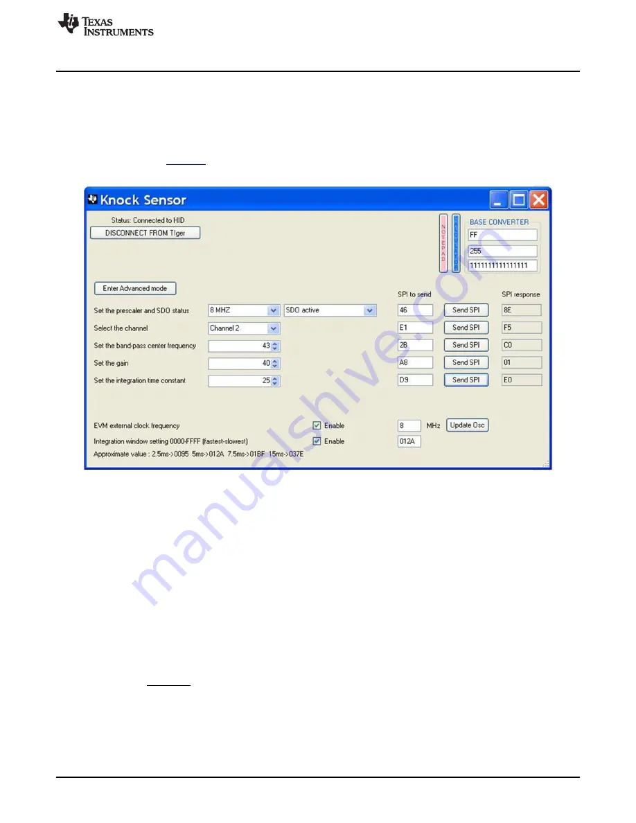
Figure 3. GUI : Advanced SPI Mode
2.3.4
Clock and Integration Window Settings
The TI communication board can generate 2 square wave forms, a high frequency one which could be
used as an external clock frequency signal, such as 8 MHz; and a low frequency one which could be used
as a integration window, such as 5 ms.
To use the external clock, check the
Enable
box and enter a desired frequency in the edit box. Press the
Update Osc
button once the settings have been updated.
To use the integration window, check the
Enable
box and enter a 4-digit hex number in the edit box. Hex
0000 is the fastest square waveform the TI communication board can produce, and hex FFFF
corresponds to the slowest waveform. The waveform is generated by the GPIO of the micro controller,
therefore the frequency is approximate. For example, hex 01C6 generates a 100-Hz square waveform,
which could be used to serve as a 5 ms integration window. An approximate formula that can be used to
calculate the hex value needed for a given time window is as follows:
(1)
5
SLIU012 – December 2015
TPIC8101 Evaluation Module
Copyright © 2015, Texas Instruments Incorporated