background image

park_D

park_Q

clarke_d

clarke_q

Valpha

Vbeta

Tb

Ta

Tc

Ipark_d

Ipark_Q

Ipark_D

Theta

Ipark_q

Mfunc_c1

Mfunc_c2

Mfunc_c3

PWM1A

PWM

DRV

MACRO

PWM1B

PWM2A

PWM2B

PWM3A

PWM3B

EV

HW

3-Phase

Inverter

PMSM

Motor

ADC

DRV

EV

HW

Ia

Vdc

Ib

AdcRslt0

AdcRslt1

clarke_a

clarke_b

park_d

park_q

PARK

MACRO

CLARKE

MACRO

SVGEN

DQ

MACRO

IPARK

MACRO

theta

watch window

Speed_Ref

PID

MACRO

Iq Reg.

IdRef (=0)

PID

MACRO

Id Reg.

QEP

DRV

EV

HW

QEPA
QEPB

Index

Elec

Theta

Direction

Speed

Speed Rpm

SPEED_FR

MACRO

u_out_q

u_out_d

i_ref_d

i_ref_q

PID

MACRO

Iq Reg.

spd_fdb

/

/

/

,

(

2

)

/

,

(

/

)

pu

base

pu

base

pu

base

base

base

pu

base

base

base

base

I

I I

V

V V

w

w w

w

f

V

w

p

=

=

=

=

Y

= Y

Y

Y

=

www.ti.com

Software Tools

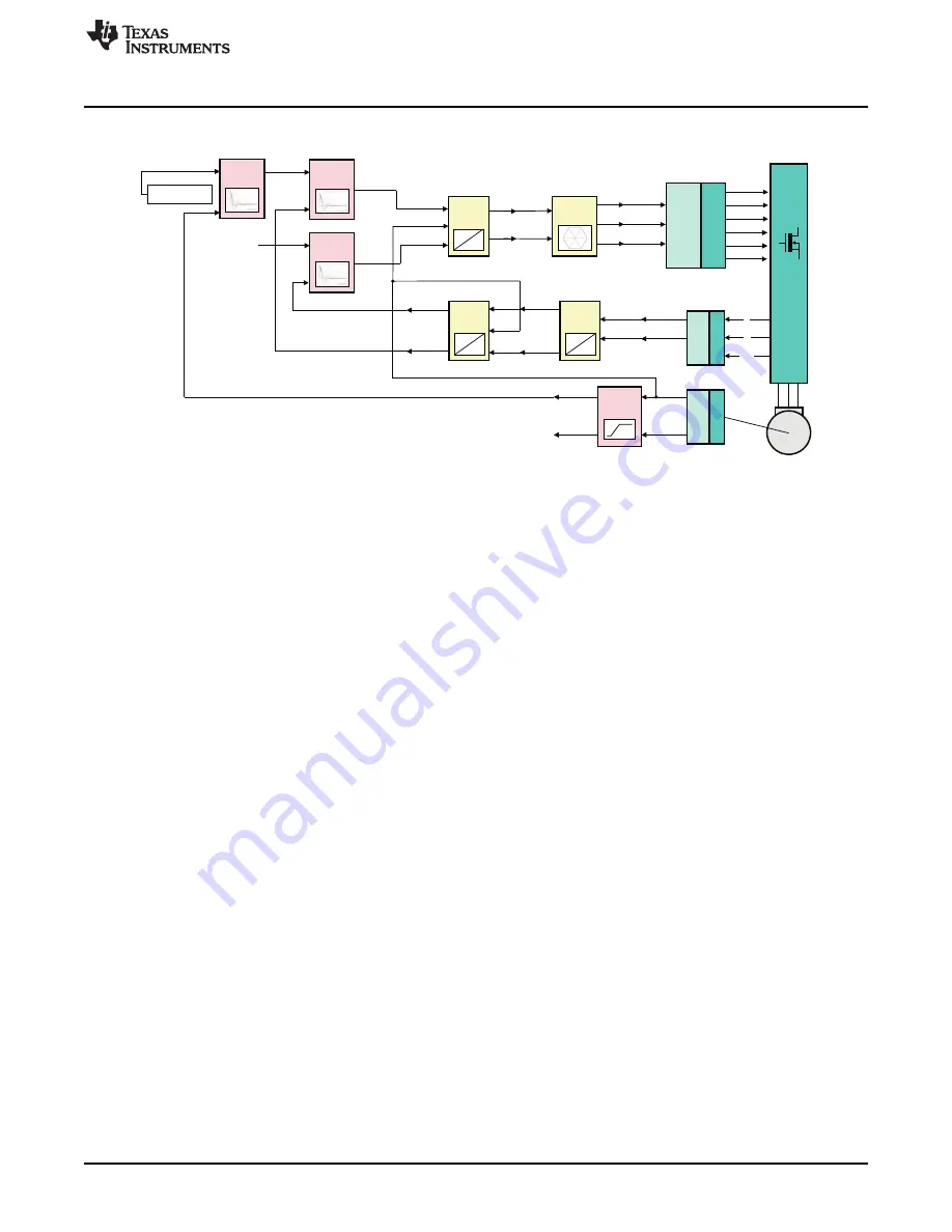
Figure 17. Build Level IV - Closed Speed Loop Test / FOC

2.5

PU System Model and Base Values

In electrical engineering, a per-unit system is the expression of system quantities as fractions of a defined
base unit quantity. Calculations are simplified because quantities expressed as per-unit (between -1 and
+1) are the same regardless of the voltage, current etc level. Advantages of using the pu system for motor
control applications include:

Once the base values are initialized in the code, the code will handle the rest and the parameter
dependency will be minimized.

Migrating to a new custom design system will be as easy as modifying the base values.

For fixed point devices, pu system allows the user to reduce the amplitude of the variables in order to
get a fractional part with a maximum precision.

Conversion of per-unit quantities to volts, ohms, or amperes requires knowledge of the base that the
per-unit quantities were referenced to. In the TI DMC systems, the base values are selected as the
maximum measurable quantity of the peak of phase voltage, current etc. by the ADC. This is directly
related to the current and voltage sensing circuits and the voltage dividers used to down-scale the actual
voltage or current quantities to ADC input voltage range, which is typically 3 to 3.3V. Later, the measured
voltage by ADCs will be converted to put quantity in the code. The calculation of the pu values can be
formulated as:

The selection of the base quantities is relative and can be any appropriate value as long as it is consistent
within the whole system. For instance, assuming that the peak of the maximum measurable phase current
is 20A on a DMC kit, the base current value can be selected as 20 where ±1pu represents ±20A in the
code.

21

SPRUGI6 – September 2010

TMS320C2000 Motor Control Primer

Submit Documentation Feedback

Copyright © 2010, Texas Instruments Incorporated

Summary of Contents for TMS320C2000

Page 1: ...TMS320C2000 Motor Control Primer User s Guide Literature Number SPRUGI6 September 2010 ...

Page 2: ...ltage levels designed for all major motor types with open source hardware support lead developers through the process of creating a complete motor control system These tools enable developers to quickly determine the processing resources required to implement basic motor control From this baseline they are then able to bring in advanced algorithms to trade off the remaining processing capacity for...

Page 3: ...solution of 32 bit Fixed point Number for Different Q format Representation GLOBAL_Q Max Val Min Val Resolution 28 7 999 999 996 8 0 000 000 004 24 127 999 999 940 128 0 000 000 060 20 2047 999 999 046 2048 0 000 000 954 A high resolution and large dynamic range is typically needed for precise control algorithm execution Motor control applications formats between Q31 to Q27 do not provide enough d...

Page 4: ...ted for a fixed or floating point variable type depending on the device type being used Consequently the code above can be run on a fixed point or a floating point device without any changes therefore enabling easy migration between floating and fixed point devices 2 1 5 Advantages of the IQMath Library for Motor Control IQmath uses the instructions present on the C28x devices in the most efficien...

Page 5: ...0 the libraries were revised with optimized macro usage for system examples using F2803x Piccolo and F2833x Delfino families and integrated into controlSUITE For more on the motor control methodology and available resources visit the TI Motor Control Site There are two releases of the math_blocks in controlSUITE the fixedv1 1 supports all three motor types and is only valid for fixed processors Th...

Page 6: ...ms software is comprehensive with many component parts To bring it all together and to allow customers to test drive many solutions quickly TI offers Code Composer Studio CCS for the C2000 platform as the Integrated Development Environment IDE Ready to run CCS projects and workspaces ensure customers are jump started into productivity quickly To complement the IDE clear module and system documenta...

Page 7: ...A digital motor control system is a good example of this interrelation of functions Figure 2 shows a typical signal flow block diagram of an AC induction motor controlled by a field oriented control strategy This is a useful representation and it is found in many classical texts on motor control However several limitations are evident when attempting to realize this diagram in software form Figure...

Page 8: ...ty can be assured across all modules Since this approach allows efficient reusability efforts which may typically be used to reinvent the wheel can be re deployed on expanding the module library base for greater functionality and features There are several DMC blocks common for 3 phase motor control in general On the other hand in most cases the difference between a sensored and sensorless system ...

Page 9: ...stationary reference frame conversion 18 impulse Impulse generator module TI AI 19 mod6_cnt Modulo 6 counter counts from state 0 TI AI through 5 and reset 20 park Park transform Stationary to rotating TI AI reference frame conversion 21 phase_volt_calc 3 phase voltage recontruction function TI AI based on PWM duty cycle inputs 22 pid_reg3 Proportional integral derivative controller TI AC with anti...

Page 10: ...ent only on the CPU core TI AI modules are typically characterized by mathematical type functions e g transforms matrix operations waveform generators etc These functions are fixed and fairly standardized and do not require configuration knowledge of peripherals or the end application itself TI AC modules also do not need knowledge of device peripherals but do need to be configured depending on th...

Page 11: ...oftware running on any devices Figure 7 Utility Debug Modules 2 3 5 Quick Module Evaluation and Testing Apart from the more obvious benefits of software modularity previously described some of the same ideas can be used to facilitate quick module testing or evaluation i e checking how applicable or how a module performs Additionally it becomes easy to test several what if scenarios by simply recon...

Page 12: ...e importantly the parameters or variables being passed and executed upon All TI applications which are part of the software offering now consist of module documents and system documents System documents always include the system block or signal flow diagram which among control engineers remains one of the most useful communication tools 2 3 6 1 Module Level DMC Library Documents The pdf files incl...

Page 13: ...athLib h IQmath lib IQ Park Variable Transformation Ds PARK MACRO Alpha Beta Sine Cosine Qs www ti com Software Tools Figure 9 Library Documents and Their Location in controlSUITE As shown in Figure 10 a target independent transformation module is described and the module inputs outputs are shown explicitly in the introduction part In addition module type target devices and related files are expla...

Page 14: ...ting reference frame GLOBAL_Q 80000000 7FFFFFFF Qs Quadrature axis Q component of transformed signal in rotating reference frame GLOBAL_Q 80000000 7FFFFFFF GLOBAL_Q valued between 1 and 30 is defined in the IQmathLib h header file Software Tools www ti com Following the module description all the necessary information is provided for C interface of the DMC module the introduction of which is shown...

Page 15: ... compared to the size of the function itself In addition when a function is inlined the compiler can optimize the function in context of the calling code Another optimization is sometimes possible to turn the function into a macro expansion This allows the compiler to optimize further under certain circumstances and produces less code and consumes fewer cycles to execute The disadvantage of this m...

Page 16: ...he last character in the line In terms of code development the macros are almost identical to C function and the user can easily convert the macro definitions to inline C functions As an example the park transformation macro definition is shown below Figure 13 A Typical Module Declaration and Macro Definition 2 4 Incremental Build Methodology Irrespective of how much planning has gone into a syste...

Page 17: ...e ISR behaves like a counter and it is updated when an interrupt is triggered and the code in the ISR is executed In order to confirm that the ISR is being triggered at each selected event this variable can be added to the watch window to see whether or not it is updating Testing some target independent modules Validating both the stimulus waveforms output of RAMP_GEN and output of SVGEN via the P...

Page 18: ...speed reference and DC Bus voltages should be adjusted carefully for PM motors so that the generated Bemf is lower than the average voltage applied to motor winding This will prevent the motor from stalling or vibrating Therefore tuning might be needed for VqTesting and SpeedRef for different motors Verify and calibrate the ADCs measurements and check ADC configuration It is necessary to make sure...

Page 19: ...ed for various load and speed conditions Most of the time a single set of coefficients does not perform well at all operating points therefore an operating point dependent PID coefficient look up table may be used to improve performance QEP drv test Build 3 also implements the angular position sensor feedback path based on the QEP driver module which outputs both the mechanical and electrical angl...

Page 20: ...error is compensated by speed PID module which needs to be tuned at this level The output of the speed PID is connected to another PID regulating Iq stator current torque generating component and the system increases or decreases the torque generation depending on the actual speed level vs speed reference For example when the system is loaded motor speed tends to reduce and the system immediately ...

Page 21: ...e the rest and the parameter dependency will be minimized Migrating to a new custom design system will be as easy as modifying the base values For fixed point devices pu system allows the user to reduce the amplitude of the variables in order to get a fractional part with a maximum precision Conversion of per unit quantities to volts ohms or amperes requires knowledge of the base that the per unit...

Page 22: ...mprehensive system covering almost all C2000 based applications The DMC projects in the Legacy and ControlSUITE are given in the table below www ti com c2000dmc dmc Table 4 Projects in controlSUITE and Legacy Motor Type Description Legacy controlSUITE 3 ph ACI Sensored Tacho i p 281x 2803x Scalar Control SVPWM 280x 3 ph ACI Sensored Tacho or Encoder 281x 2803x Field Oriented Control 280x SVPWM 3 p...

Page 23: ...thing needed for C2000 system development controlSUITE s main features include controlSUITE desktop graphical navigation tool Manual or auto update to insure synchronization with latest content Devices first level device initialization system tasking and example projects Libraries foundational libraries and utilities for math DSP IQMath CLA floating point flash boot and specific applications Kits ...

Page 24: ...M motor and sensorless trapezoidal control on a BLDC motor that are available from the TI website Note that the performance of the motor with the flashed image is not a metric of quality of control and performance levels achievable using the TI DMC library The GUI allows the user to select the motor type visually inspect some waveforms e g current voltage back emf etc numerically watch bus voltage...

Page 25: ... are given in this section These can be found in controlSUITE Desktop Kits Documentation or directly C ti controlSUITE development_kits HVMotorCtrl PfcKit_v1 3 HVPM_Sensored Docs Or for Legacy at C tidcs DMC c28 v32x sys pmsm3_1_280x doc 2 7 3 Hardware Guide and How to Run Guides The hardware guide describes the target kit contents and hardware details and explains the functions and locations of j...

Page 26: ...h window help the user to monitor and reduce noise level ripple transient overshoot etc DMC Code Graph Window Watch Window Software Tools www ti com Pin descriptions Associated datasheets This package helps the users to build their own boards using TI design and layout Found in controlSUITE Desktop Kits Folders or directly C ti controlSUITE development_kits HVMotorCtrl PfcKit_v1 3 HVMotorCtrl PFC ...

Page 27: ...roject as they will need to be customized to your specific implementation For controlSUITE the first DRIVER implementations were done for the High Voltage Kit so those projects also point to the controlSUITE path but you will notice for subsequent kits like the Low Voltage versions the drivers were brought into the specific project and modified as needed These DRIVER blocks additionally use files ...

Page 28: ... to view these variables in real world units so that they can be sent externally to a data logger or so the program is easier to use iii Project specific events such as updating coefficients or enabling disabling an output 2 Initialize DMCLib modules that require initialization 3 ISR PIE servicing 4 Enter idle background loop A Tasks 1ms A1 Not used in this project A2 Not used in this project A3 N...

Page 29: ...ree most common types of brushless motors AC induction brushless DC and permanent magnet synchronous motors The kit has all the features to implement sensored and sensorless control of each motor type The software and hardware for the kit is completely open source The kit has the following key features 3 phase inverter stage 350V DC max input voltage 1 5 kW maximum load QEP and CAP inputs availabl...

Page 30: ... this baseline they are then able to bring in advanced algorithms to trade off the remaining processing capacity for greater accuracy better performance higher power efficiency control of multiple motors and a various other options In this way developers can architect systems specifically optimized for their application constraints and requirements The low voltage kit has the following key feature...

Page 31: ...2 V 12 V QEP 3 HOST Vac PFC 2PhIL PWM 5B PWM 5A PWM 5 A B www ti com Hardware Tools Miscellaneous On board isolated JTAG emulation Over current and over voltage protection for the PFC stage and over current protection for each rectifier section UART communication header available for host control Hardware Developer s Package is available and includes schematics bill of materials Gerber files etc T...

Page 32: ...ch statements TI products are not authorized for use in safety critical applications such as life support where a failure of the TI product would reasonably be expected to cause severe personal injury or death unless officers of the parties have executed an agreement specifically governing such use Buyers represent that they have all necessary expertise in the safety and regulatory ramifications o...

Reviews: