Board Connectors and Components
8
SBOU152A – July 2015 – Revised September 2019
Copyright © 2015–2019, Texas Instruments Incorporated
TMP461EVM Hardware Overview and Setup
2.1.2 Pushbutton Switch – SW1
The SW1 push button can bring the MSP430 into BSL mode and allow the user to upgrade the firmware
with the combination of the USB connector. Press and hold the switch SW1 next to the USB connector
while plugging the USB cable from the board to the PC to bring the MSP430 into BSL mode.
2.1.3 LEDs – D3, D5, D6
D3 is a green LED that can indicate when the EVM has power and can turn on after plugging in the board.
The D5 LED can indicate a THERM fault and will turn on when the device detects a THERM fault and
brings the pin LOW. D6 does the same function but for the ALERT/THERM2 pin. Both these LEDs are
red.
2.1.4 Remote BJT – Q1
Q1 is a MMBT3904LP NPN BJT. This is used as the remote temperature sensor on the EVM. The
MMBT3904LP typically has an N-factor of about 1.0042. The TMP461 assumes an N-Factor of 1.008,
which can cause a temperature error in the remote temperature reading. The GUI automatically sets the
N-Factor correction register to 1.0042 to compensate for this. If the device is reset, it will set the N-Factor
correction register back to the default value or 1.008 and a temperature error may be seen. If a remote
temperature error is seen, use the N-Factor correction feature to adjust the temperature reading. The
MMBT3904LP can also be broken off to allow the engineer to connect a different temperature remote to
the device.
2.1.5 Address Jumpers – J3, J4
J3 and J4 are used for setting the I2C address of the TMP461. J3 is used to set the A0 pin, and J4 is
used to set the A1 pin.
2.2
Hardware Setup
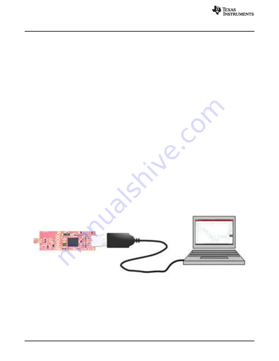
The TMP461EVM hardware consists of the USB2ANY Platform and the TMP461 altogether on one single
board. The unit is easily connected through a USB connector into the computer, as shown in
The green LED (D3) should turn on after the EVM is connected to the computer, confirming that the EVM
is powered. The engineer can either use the included jumpers to connect the middle pin to one of adjacent
headers to set the pin to either V+ or GND, or they can leave the pin floating for the desired I2C address.
Figure 2-2. Hardware Setup


