www.ti.com
TMP102 Documentation
6.2
PCB Layout
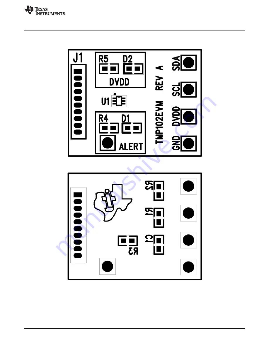
Figure 24
and
Figure 25
show the PCB layout of the TMP102EVM.
Figure 24. TMP102EVM PCB Top Layer (Component Side)
Figure 25. TMP102EVM PCB Bottom Layer
19
SBOU114
–
August 2011
TMP102EVM Evaluation Board and Software Tutorial
Submit Documentation Feedback
Copyright
©
2011, Texas Instruments Incorporated