Schematics, PCB Layout, and Bill of Materials
www.ti.com
12
SBOU209A – August 2019 – Revised March 2020
Submit Documentation Feedback
Copyright © 2019–2020, Texas Instruments Incorporated
TMCS1100EVM
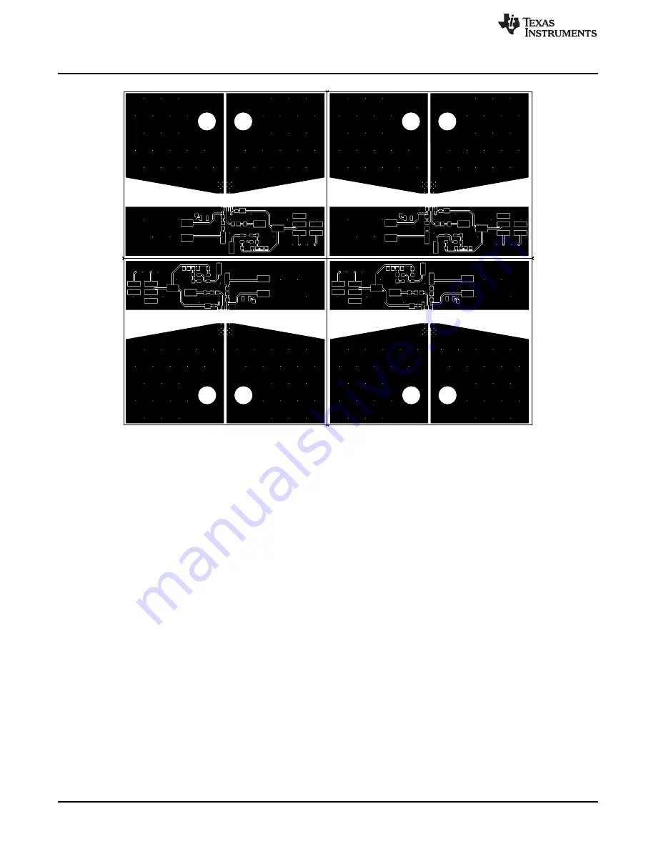
Figure 5. Top Layer
Page 1: ...ation and use of the TMCS1100 evaluation module EVM This EVM is designed to evaluate the performance of the TMCS1100 voltage output isolated bidirectional Hall effect current sense amplifiers in a var...
Page 2: ...rcuitry 6 4 Operation 8 4 1 Measurements 9 4 2 Advanced Measurement Tips 9 5 Schematics PCB Layout and Bill of Materials 10 5 1 Schematics 10 5 2 PCB Layout 11 5 3 Bill of Materials 15 List of Figures...
Page 3: ...Area Safety a Keep work area clean and orderly b Qualified observer s must be present anytime circuits are energized c Effective barriers and signage must be present in the area where the TI HV EVM an...
Page 4: ...n options Table 1 TMCS1100Ax Device Summary Product Gain TMCS1100A1 50 mV A TMCS1100A2 100 mV A TMCS1100A3 200 mV A TMCS1100A4 400 mV A 2 1 Kit Contents Table 2 lists the contents of the TMCS1100EVM k...
Page 5: ...etic compatibility EMC testing The TMCS1100EVM consists of one PCB that can be snapped apart into four individual segments one for each of the four gain variants TMCS1100A1 TMCS1100A2 TMCS1100A3 TMCS1...
Page 6: ...SOURCE R5x is left open and unpopulated by default 3 2 5 Measurement Connector J2x is an additional connector for measuring VREF Source VCC and VOUT J2x also provides a connection for measuring board...
Page 7: ...e the largest appropriate output swing and to minimize error 3 2 9 Temperature Sensor U2x is a temperature sensor that is not required for TMCS1100 operation However U2x provides the option of measuri...
Page 8: ...upply and REF for VREF supply Short the GND terminals for the cold and REF supplies together The hot supply can be isolated and at a different potential Figure 1 Low Side Unidirectional Setup Figure 2...
Page 9: ...rrent passing through the leadframe of the DUT 4 2 Advanced Measurement Tips To assess whether the expected load matches the measured load use a precision shunt resistor rated for the maximum intended...
Page 10: ...are not intended to be used for manufacturing TMCS1100EVM PCBs 5 1 Schematics Figure 3 shows the schematic of the A1 sub board on the TMCS1100EVM PCB Only the schematic for the A1 50 mV A gain variant...
Page 11: ...rials 11 SBOU209A August 2019 Revised March 2020 Submit Documentation Feedback Copyright 2019 2020 Texas Instruments Incorporated TMCS1100EVM 5 2 PCB Layout Figure 4 through Figure 7 illustrate the PC...
Page 12: ...atics PCB Layout and Bill of Materials www ti com 12 SBOU209A August 2019 Revised March 2020 Submit Documentation Feedback Copyright 2019 2020 Texas Instruments Incorporated TMCS1100EVM Figure 5 Top L...
Page 13: ...com Schematics PCB Layout and Bill of Materials 13 SBOU209A August 2019 Revised March 2020 Submit Documentation Feedback Copyright 2019 2020 Texas Instruments Incorporated TMCS1100EVM Figure 6 Bottom...
Page 14: ...tics PCB Layout and Bill of Materials www ti com 14 SBOU209A August 2019 Revised March 2020 Submit Documentation Feedback Copyright 2019 2020 Texas Instruments Incorporated TMCS1100EVM Figure 7 Bottom...
Page 15: ...4 Header 2 54mm 3x1 Gold SMT Header 2 54mm 3x1 SMT TSM 103 01 L SV P TR Samtec J2A J2B J2C J2D 4 Header 2 54mm 3x2 Gold SMT Header 2 54mm 3x2 SMT TSM 103 01 L DV Samtec MP1 MP2 2 Passivated 18 8 Stai...
Page 16: ...Texas Instruments U1B 1 TMCS1100A2DT D0008A SOIC 8 D0008A TMCS1100A2DT Texas Instruments U1C 1 TMCS1100A3DT D0008A SOIC 8 D0008A TMCS1100A3DT Texas Instruments U1D 1 TMCS1100A4DT D0008A SOIC 8 D0008A...
Page 17: ...n History NOTE Page numbers for previous revisions may differ from page numbers in the current version Changes from Original August 2019 to A Revision Page Added the on board temperature sensor to the...
Page 18: ...e resources are subject to change without notice TI grants you permission to use these resources only for development of an application that uses the TI products described in the resource Other reprod...