Texas Instruments TMAG5115 User Manual Download Page 10

3.2.3.2 MCT8316ZTEVM Quick Start Guide

The MCT8316ZTEVM requires a power supply source, which has a recommended operating range from a 4.5 V 
to 35 V. To setup and power the EVM, use the following the sequence:

1. Connect motor phases to A, B, and C on connector J13.
2. Connect Hall sensors to J11 and use HALL_PWR_SEL jumper J11 to select the supply as 3.3 V from buck 

or use an external supply on connected to J12. Ensure the MODE resistors are set correctly to use the 
appropriate Hall sensor configuration as described in 

MCT8316Z datasheet

.

a. If using the boards pullup resistors, populate J8–J10 with shunt jumpers to enable pullups. Connect the 

single-ended inputs to only the HPx pins on connector J11. This is the default of the MCT8316ZTEVM.

3. Ensure resistors are populated in H/W variant resistors for desired hardware settings.
4. DO NOT TURN ON the power supply yet. Connect the motor supply to VBAT or VM and PGND on 

connector J7.
a. To enable reverse polarity protection and Pi filter, connect to VBAT.
b. To disable reverse-polarity protection and the Pi filter, connect to VM.

5. Select J3 to 5V_USB and J5 to 3V3COM to power MSP430 from USB power supply.
6. Connect the micro-USB cable to the computer.
7. Turn the potentiometer fully clockwise to set the motor to zero speed upon power up.
8. Turn on the motor power supply.
9. Use the potentiometer to control the speed of the motor and the switches to disable the motor driver, change 

the direction, or apply a brake to the motor. Optionally, use the GUI (as shown in the 

MCT8316ZTEVM 

User's Guide

) to monitor real-time speed of the motor, put the MCT8316ZT into a low-power sleep mode, 

and read status of the LEDs.

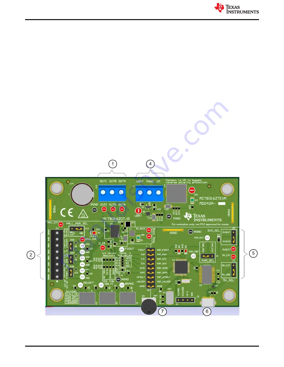
Figure 3-8. Reference for MCT8316ZTEVM Quick Start Guide

EVM Operation

www.ti.com

10

TMAG5115 Evaluation Module

SBAU410 – OCTOBER 2022

Submit Document Feedback

Copyright © 2022 Texas Instruments Incorporated

Summary of Contents for TMAG5115

Page 1: ...rd PCB layouts and a complete bill of materials BOM Table of Contents 1 Overview 2 1 1 TMAG5115EVM Kit Contents 2 1 2 Related Documentation from Texas Instruments 2 2 TMAG5115EVM Hardware 3 3 EVM Oper...

Page 2: ...mT 4 mT 1 1 TMAG5115EVM Kit Contents Table 1 2 lists the contents of the TMAG5115EVM kit Contact the Texas Instruments Product Information Center if any components are missing TI highly recommends che...

Page 3: ...re to set up and use the TMAG5115EVM 3 1 Quick Start Setup 1 Power up the EVM using a variable power supply a Set the power supply voltage to the desired setting between 3 V and 12 V Do not turn on th...

Page 4: ...algorithm for sensored motor control The TMAG5115 reacts to the magnetic field generated by the permanent magnets located on the rotor of the magnet As the motor spins the three Hall sensors create a...

Page 5: ...Figure 3 3 Six Step Motor Commutation Control Scheme www ti com EVM Operation SBAU410 OCTOBER 2022 Submit Document Feedback TMAG5115 Evaluation Module 5 Copyright 2022 Texas Instruments Incorporated...

Page 6: ...e from the motor To remove the backplate remove the four screws found on the backside of the motor opposite to the motor s shaft See Figure 3 4 After the screws are removed the backplate of the motor...

Page 7: ...sors to the bottom of the housing and remove the board See Figure 3 5 Figure 3 5 Hall Sensor Board Removal www ti com EVM Operation SBAU410 OCTOBER 2022 Submit Document Feedback TMAG5115 Evaluation Mo...

Page 8: ...eturn the screws that were removed in the previous step and tighten See Figure 3 6 for TMAG5115EVM alignment inside the motor Figure 3 6 TMAG5115EVM on NEMA17 Motor Module EVM Operation www ti com 8 T...

Page 9: ...are populated on the EVM board a You can remove the pullup resistors on the TMAG5115EVM if your motor driver includes pullup resistors for the Hall effect sensor inputs 3 2 3 Example Using MCT8316ZTE...

Page 10: ...4 DO NOT TURN ON the power supply yet Connect the motor supply to VBAT or VM and PGND on connector J7 a To enable reverse polarity protection and Pi filter connect to VBAT b To disable reverse polari...

Page 11: ...ferred resistors R1 R3 can be removed from the TMAG5115EVM If this is done ensure to follow steps 2 a from the above section 2 Connect the TMAG5115EVM wires into connector J11 on MCT8315ZTEVM a Connec...

Page 12: ...put For more information on the MCT8316ZTEVM refer to the MCT8316ZTEVM User s Guide and the MCT8316Z product page For more information on other TI BLDC motor drivers go to ti com BLDC EVM Operation ww...

Page 13: ...QBL4208 41 04 006 Mouser Link Newark Link 5 TMAG5115EVM Circuitry This section summarizes the TMAG5115EVM components R1 R2 and R3 function as pullup resistors for the open drain output of the TMAG511...

Page 14: ...5115B1CQDBZR U1 VCC 1 OUT 2 GND 3 TMAG5115B1CQDBZR U3 VCC 1 OUT 2 GND 3 TMAG5115B1CQDBZR U2 2 1 D1 CS63CGT1C 2MA 1 2 D3 CS63BR6C 2 1 D2 CS63CY2C 16V 0 1uF C1 16V 0 1uF C2 16V 0 1uF C3 1 0uF 16V C7 1 0...

Page 15: ...5115EVMBottom Copper Figure 6 4 TMAG5115EVM Top Overlay Figure 6 5 TMAG5115EVM Bottom Overlay www ti com TMAG5115EVM Schematic and PCB Layout SBAU410 OCTOBER 2022 Submit Document Feedback TMAG5115 Eva...

Page 16: ...63BR6C ChromeLED R1 R2 R3 3 10k RES 10 k 5 0 1 W 0603 0603 RC1608J103CS Samsung Electro Mechanics R4 R5 R6 3 2 2k RES 2 2 k 5 0 063 W 0402 0402 CRCW04022K20JNED Vishay Dale U1 U2 U3 3 Digital Latch Ha...

Page 17: ...ther than TI b the nonconformity resulted from User s design specifications or instructions for such EVMs or improper system design or c User has not paid on time Testing and other quality control tec...

Page 18: ...These limits are designed to provide reasonable protection against harmful interference in a residential installation This equipment generates uses and can radiate radio frequency energy and if not in...

Page 19: ...instructions set forth by Radio Law of Japan which includes but is not limited to the instructions below with respect to EVMs which for the avoidance of doubt are stated strictly for convenience and s...

Page 20: ...any interfaces electronic and or mechanical between the EVM and any human body are designed with suitable isolation and means to safely limit accessible leakage currents to minimize the risk of electr...

Page 21: ...R DAMAGES ARE CLAIMED THE EXISTENCE OF MORE THAN ONE CLAIM SHALL NOT ENLARGE OR EXTEND THIS LIMIT 9 Return Policy Except as otherwise provided TI does not offer any refunds returns or exchanges Furthe...

Page 22: ...change without notice TI grants you permission to use these resources only for development of an application that uses the TI products described in the resource Other reproduction and display of thes...

Reviews: