www.ti.com
PCB Layout
7
SBVU057 – December 2019
Submit Documentation Feedback
Copyright © 2019, Texas Instruments Incorporated
TLV751-EVM Evaluation Module
4
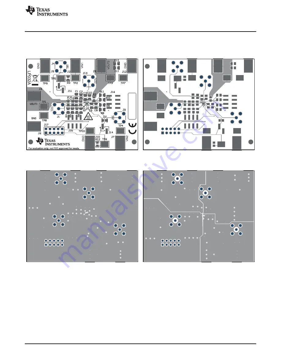
PCB Layout
Figure 2
to
Figure 6
illustrate the PCB layout for this EVM.
Figure 2. Assembly Layer
Figure 3. Top Layer Routing
Figure 4. First Middle Layer
Figure 5. Second Middle Layer


