2.6.6
Digital Configuration
EVM + PC
www.ti.com
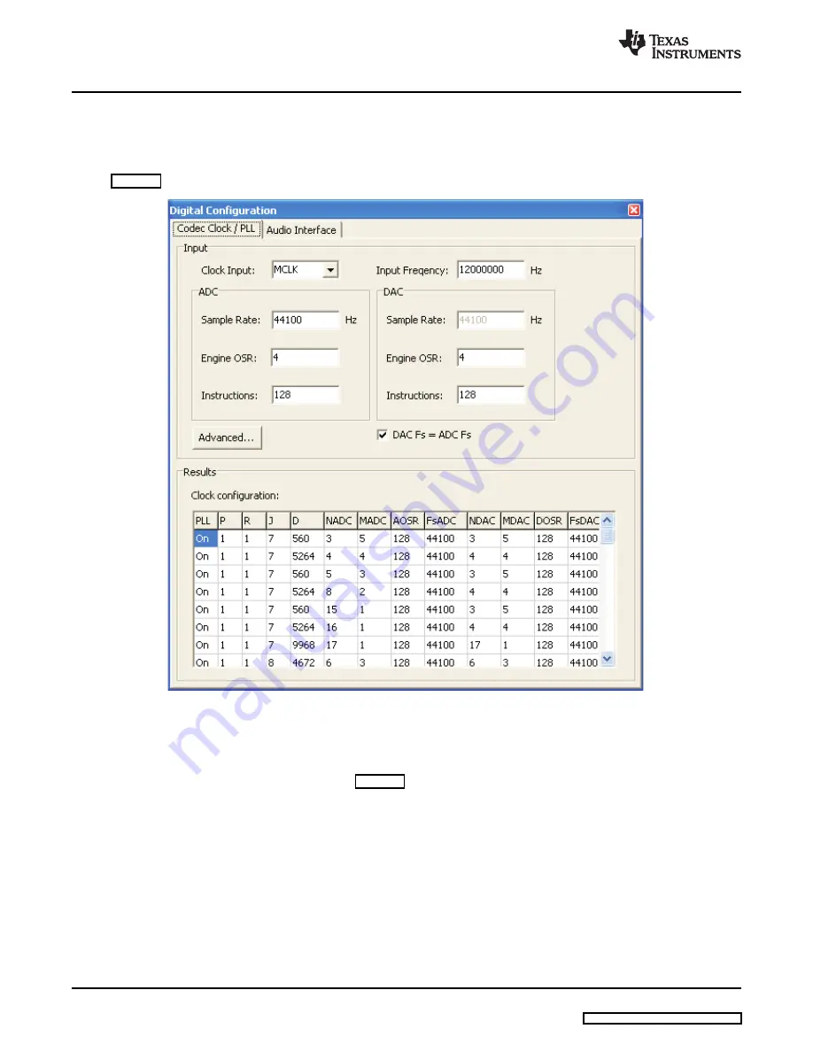
The digital configuration dialog gives access to the codec clock and PLL settings as well as the audio
interface settings.
To open the digital configuration dialog, navigate to the clock and digital signal routing diagram (see
) and click on the “Internal Clock Gen Module” active object.
Figure 7. Digital Configuration: Codec Clock / PLL
The digital configuration dialog contains two tabs, one for the Codec Clock / PLL settings and one for the
Audio Interface settings.
The Codec Clock / PLL settings tab (see
) enables simple generation of PLL and clock divider
settings based on the available input frequency and the desired sample rate:
1. Choose the clock input using the Clock Input drop down box.
2. Type the available input frequency in the Input Frequency edit field.
3. Type the desired sample rate in the Sample Rate edit field of the ADC. By default, the DAC sample
rate equals the ADC sample rate. Uncheck DAC Fs = ADC Fs and enter the DAC sample rate for
different sample rates.
4. The Engine OSR and Instructions fields affect the miniDSP. Please contact your TI representative for
further information about the miniDSP.
5. The Results list shows all clock settings that fulfill the chosen parameters. Double click on one of the
results to program the TLV320AIC3111 with the new settings.
Each result has the following columns:
12
TLV320AIC3111 EVM
SLAU285 – July 2009


