


4.2
Main Software Screen With Indicators and Functions
TLV320AIC3007EVM Software
www.ti.com
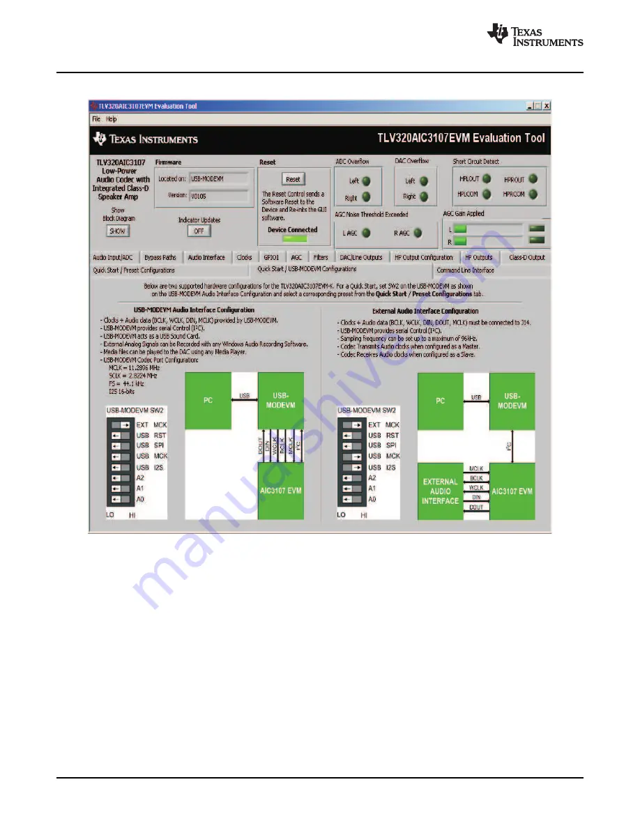
Figure 4. Main Software Screen
Figure 4
illustrates the main screen of the EVM software. The indicators and buttons located above the
tabbed section of the front page are visible regardless of which tab is currently being selected.
The firmware box indicates from where the firmware being used is operating. In this release, the firmware
is on the USB-MODEVM, so the user sees
USB-MODEVM
in the box labeled
Located on:
. The version of
the firmware appears in the
Version
box below this.
To the right, the next group box contains controls for resetting the TLV320AIC3007EVM. A software reset
can be done by writing to a register in the TLV320AIC3007EVM; this is accomplished by clicking the
button labeled
Reset
.
Near the
Firmware
box, the
Device Connected
LED is green when the EVM is connected. If the indicator
is red, the EVM is not properly connected to the PC. Disconnect the EVM, and verify that the drivers were
correctly installed. Then reconnect, and try restarting the software.
On the upper right portion of the screen are located several indicators which provide the status of various
portions of the TLV320AIC3007. Pressing the
Indicator Updates
button activates these indicators. These
indicators, as well as the other indicators on this panel, are updated only when the software's front panel
is inactive, once every 20 ms.
10
TLV320AIC3007EVM-K
SLAU286 – June 2009
Submit Documentation Feedback