www.ti.com
1.3
Input/Output Connector Descriptions
Introduction
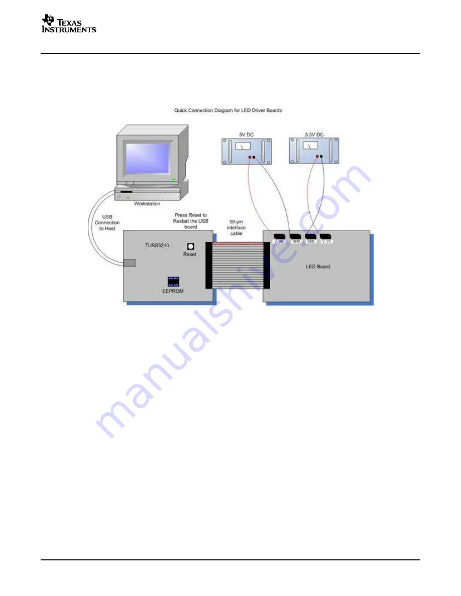
Attach the 3.3-volt (500-mA) power supply to the LED board between J4 (V_CC) and J7 (GND).
Connect the host computer to the TUSB3210 board using the USB cable. If the computer is running, a
message about installing new hardware may be displayed. Follow the on-screen instructions and allow
windows to install the default drivers for this device. Note that the USB board appears to windows as a
generic human interface device (such as a keypad or a mouse), so there is no custom driver to install.
Figure 1. Hardware Setup
1.3.1
J1 – Interface Connector
J1 provides easy access to all signals necessary to control the TLC5940EVM. This connector is useful for
interfacing the customer controller board to the EVM. Refer to the data sheet for a more detailed
description of each signal’s function. Do not actively drive the same signals on J1 and J3 at the same
time. As shown on the schematic, these signals from J1 are buffered before reaching the TLC5940 ICs.
SLVU139 – September 2005
TLC5940 EVM
3
Summary of Contents for TLC5940 EVM
Page 9: ...www ti com Board Layout Figure 3 Top Layer Routing SLVU139 September 2005 TLC5940 EVM 9 ...
Page 10: ...www ti com Board Layout Figure 4 Layer 2 Routing TLC5940 EVM 10 SLVU139 September 2005 ...
Page 11: ...www ti com Board Layout Figure 5 Layer 3 Routing SLVU139 September 2005 TLC5940 EVM 11 ...
Page 12: ...www ti com Board Layout Figure 6 Bottom Layer Routing TLC5940 EVM 12 SLVU139 September 2005 ...


