Green
1
2
D6
MDIO_CLK_1
MDIO_DATA_1
GND
GND
D1+
1
D1-
2
NC
6
NC
7
NC
9
NC
10
D2+
4
D2-
5
GND
3
GND
8
U7
TPD4E05U06DQA
PHY1_TD_A_P
PHY1_TD_A_N
PHY1_TD_B_P
PHY1_TD_B_N
PHY1_TD_C_P
PHY1_TD_C_N
PHY1_TD_D_P
PHY1_TD_D_N
GND
PHY1_TD_C_P
PHY1_TD_C_N
PHY1_TD_D_P
PHY1_TD_D_N
PHY_RESETn
PHY1_INTPWDN
PHY1_CLKOUT
2
3
4
1
5
6
7
8
9
10
11
12
J4
43202-8916
Yellow
1
2
D4
Red
1
2
D5
GND
V11phy
PHY1_X_D_N
PHY1_X_D_P
PHY1_X_C_N
PHY1_X_C_P
PHY1_X_D_P
PHY1_X_D_N
PHY1_X_C_P
PHY1_X_C_N
PHY1_X_B_N
PHY1_X_B_P
PHY1_X_A_P
PHY1_X_A_N
75.0
R24
75.0
R22
75.0
R32
75.0
R37
PHY1_EARTH
1000pF
C33
PHY1_EARTH
PHY1_TD_A_P
PHY1_TD_A_N
PHY1_TD_B_P
PHY1_TD_B_N
PHY1_TD_C_P
PHY1_TD_C_N
PHY1_TD_D_P
PHY1_TD_D_N
GND
10.0k
R21
560
R25
22
R35
DNP
1.00M
R36
DNP
560
R26
560
R27
0.1µF
C27
0.1µF
C28
0.1µF
C29
0.1µF
C30
Check Vddio needed before CAP
GND
PHY1_TD_C_P
PHY1_TD_C_N
PHY1_TD_D_P
PHY1_TD_D_N
D1+
1
D1-
2
NC
6
NC
7
NC
9
NC
10
D2+
4
D2-
5
GND
3
GND
8
U8
TPD4E05U06DQA
DNP
PHY1_X_C_P
PHY1_X_C_N
PHY1_X_D_P
PHY1_X_D_N
4.7k
R23
1000pF
C26
1000pF
C25
GND
GND
PHY1_EARTH
27pF
C31
DNP
27pF
C32
DNP
GND
GND
GND
4.7k
R29
Vddio
TCT1
1
TD1+
2
TD1-
3
TCT2
4
TD2+
5
TD2-
6
TCT3
7
TD3+
8
TD3-
9
TCT4
10
TD4+
11
TD4-
12
MX4-
13
MX4+
14
MCT4
15
MX3-
16
MX3+
17
MCT3
18
MX2-
19
MX2+
20
MCT2
21
MX1-
22
MX1+
23
MCT1
24
T1
HX5008FNL
1
2
25 MHz
Y1
ABM3-25.000MHZ-D2Y-T
DNP
1000pF
C34
DNP
GND
PHY1_EARTH
0
R171
CDC_CLK1
0
R170
DNP
TD_P_A
2
TD_M_A
3
TD_P_B
5
TD_M_B
6
TD_P_C
10
TD_M_C
11
TD_M_D
14
TD_P_D
13
RBIAS
15
MDC
20
MDIO
21
INT/PWDN
60
RESET
59
XI
19
XO
18
CLK_OUT
22
JTAG_CLK
25
JTAG_TDO
26
JTAG_TDI
28
JTAG_TRSTN
24
LED_2
61
LED_1
62
LED_0
63
VDDA1P8
17
VDDA1P8
64
VDD1P1
8
VDD1P1
29
VDD1P1
42
VDD1P1
58
GND
65
JTAG_TMS
27
4.7pF
C261
GND
4.7pF
C262
4.7pF
C263
GND
4.7pF
C264
4.7pF
C265
GND
4.7pF
C266
4.7pF
C267
GND
4.7pF
C268
PHY1_TD_A_P
PHY1_TD_A_N
PHY1_TD_B_P
PHY1_TD_B_N
PHY1_TD_C_P
PHY1_TD_C_N
PHY1_TD_D_P
PHY1_TD_D_N
Copyright © 2017, Texas Instruments Incorporated
System Overview
13
JAJU324B – March 2015 – Revised July 2017
翻訳版
—
最新の英語版資料
http://www-s.ti.com/sc/techlit/TIDU832
Copyright © 2015–2017, Texas Instruments Incorporated
EMI/EMC
規格準拠、産業用温度範囲のデュアルポート・ギガビット・イーサネットの
リファレンス・デザイン
2.3.1.1.3
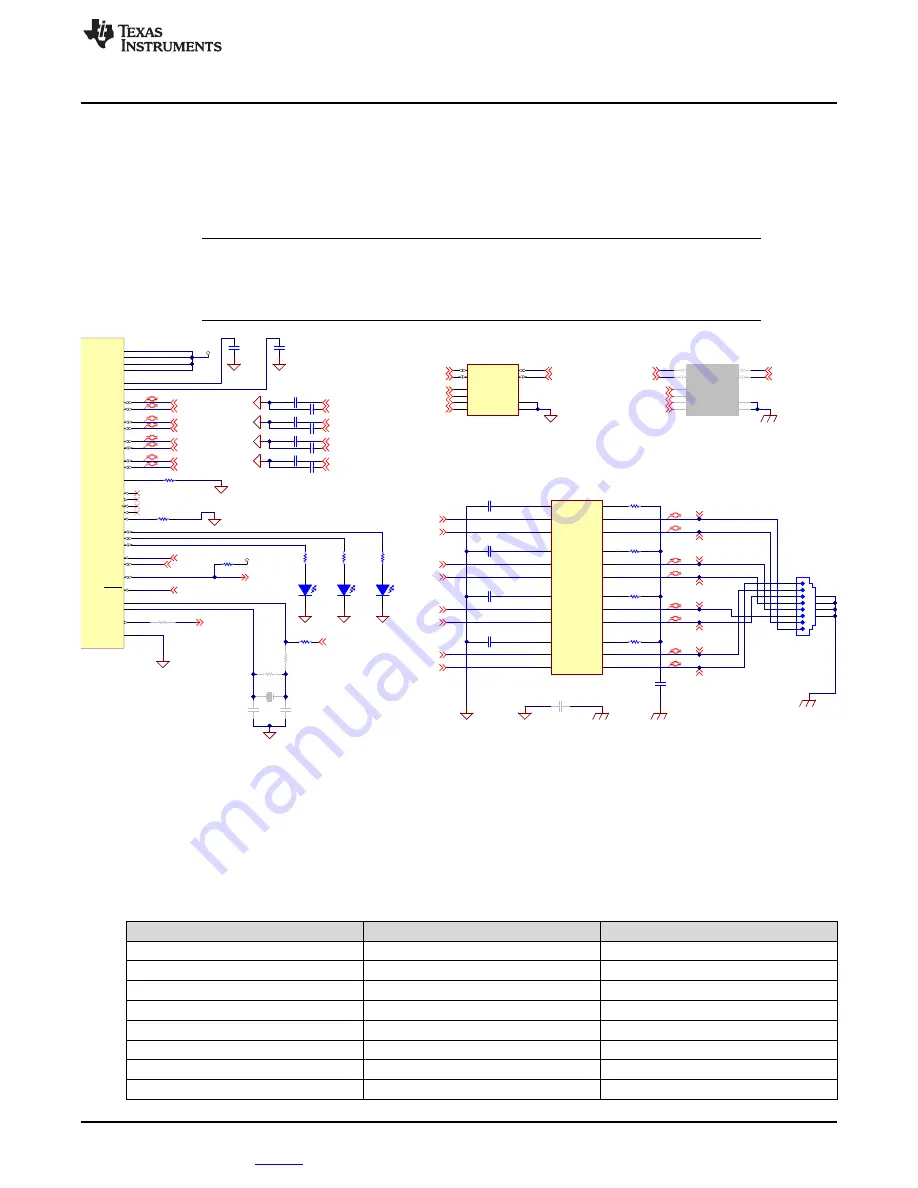
Interface From PHY to RJ-45
The transformer used in the MDI connection provides DC isolation between local circuitry and the network
cable. The center tap of the isolated winding has a "Bob Smith" termination through a 75-
Ω
and a 1000-pF
capacitor-to-chassis ground. The termination capacitor should be voltage rated to at least 2 kV. The Bob
Smith termination reduces noise resulting from common mode current flows.
注
注
:
A TVS diode has been placed each between the DP83867IR and the transformer and the
transformer and the RJ45 jack. This was a test and debug option only and the position
between the DP83876IR and the magnetics showed slightly better results in EMC and EMI,
as shown in
図
図
7. Schematic of Media Dependent Interface of ETH1
The trace length that needs to be considered is from RJ45 to magnetic and from magnetic to DP8867IR,
for these signals they are differential pairs. This means that the signals needs to be routed differentially as
long as possible without making the traces longer than necessary. To ensure data integrity, the trace’s
difference should be below 10 mil (0.254 mm).
表
表
8. Differential Signal Trace Length From PHY to Magnetic and Magnetic to RJ45 Jack
MEDIA DEPENDENT INTERFACE
RJ45 TO MAGNETIC (mm)
MAGNETIC TO DP8867IR (mm)
PHY1 Differential pair A (N,P)
13.0123 (N), 13.0708 (P)
10.0302 (N), 10.0302 (P)
PHY1 Differential pair B (N,P)
13.1709 (N), 13.3115 (P)
10.0223 (N), 10.0223 (P)
PHY1 Differential pair C (N,P)
13.1321 (N), 13.0146 (P)
10.0175 (N), 10.0082 (P)
PHY1 Differential pair D (N,P)
13.0804 (N), 13.0003 (P)
10.0163 (N), 10.0163 (P)
PHY2 Differential pair A (N,P)
12.9469 (N), 13.0056 (P)
13.3910 (N), 13.4938 (P)
PHY2 Differential pair B (N,P)
12.9398 (N), 13.0815 (P)
13.1988 (N), 13.1047 (P)
PHY2 Differential pair C (N,P)
13.0899 (N), 13.0409 (P)
13.0679 (N), 13.1622 (P)
PHY2 Differential pair D (N,P)
13.1864 (N), 13.1063 (P)
13.3252 (N), 13.2272 (P)


