August 29, 2012
21
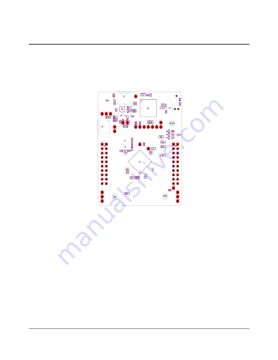
Component Locations
Plots of the top-side component locations are shown in Figure B-1 and the board dimensions are shown in Figure B-2.
Figure B-1. Stellaris® LaunchPad Component Locations (Top View)
A P P E N D I X B
Page 1: ...EK LM4F120XL UM 01 Copyright 2012 Texas Instruments SMPU289 User s Manual Stellaris LM4F120 LaunchPad Evaluation Board ...
Page 2: ... and StellarisWare are registered trademarks of Texas Instruments ARM and Thumb are registered trademarks and Cortex is a trademark of ARM Limited Other names and brands may be claimed as the property of others Texas Instruments 108 Wild Basin Suite 350 Austin TX 78746 http www ti com stellaris ...
Page 3: ...r USB Expansion Buttons and LED Schematic on page 18 10 Power Management Schematic on page 19 13 Stellaris In Circuit Debug Interface ICDI Schematic on page 20 14 Chapter 3 Software Development 15 Software Description 15 Source Code 15 Tool Options 15 Programming the Stellaris LaunchPad Evaluation Board 15 Appendix A Schematics 17 Appendix B Component Locations 21 Appendix C Bill of Materials BOM ...
Page 4: ... 29 2012 List of Figures Figure 1 1 Stellaris LM4F120 LaunchPad Evaluation Board 6 Figure 2 1 Stellaris LaunchPad Evaluation Board Block Diagram 9 Figure B 1 Stellaris LaunchPad Component Locations Top View 21 Figure B 2 Stellaris LaunchPad Dimensions 22 ...
Page 5: ...ls 10 Table 2 2 User Switches and RGB LED Signals 10 Table 2 3 J1 Connector 11 Table 2 4 J2 Connector 11 Table 2 5 J3 Connector 12 Table 2 6 J4 Connector 12 Table 2 7 Stellaris In Circuit Debug Interface ICDI Signals 14 Table 2 8 Virtual COM Port Signals 14 Table C 1 EK LM4F120 Bill of Materials 23 ...
Page 6: ...n module The Stellaris LaunchPad also features programmable user buttons and an RGB LED for custom applications The stackable headers of the Stellaris LM4F120 LaunchPad BoosterPack XL Interface demonstrate how easy it is to expand the functionality of the Stellaris LaunchPad when interfacing to other peripherals with Stellaris BoosterPacks and MSP430 BoosterPacks Figure 1 1 shows a photo of the St...
Page 7: ... Stellaris Peripheral Driver Library Software applications are loaded using the on board Stellaris In Circuit Debug Interface ICDI See Chapter 3 Software Development on page 20 for the programming procedure The StellarisWare Peripheral Driver Library Software Reference Manual contains specific information on software structure and function For more information on Project 0 go to the www ti com ste...
Page 8: ...e the on board LM4F120H5QR microcontroller as its processor See Microcontroller USB Expansion Buttons and LED Schematic on page 18 on page 10 in Chapter 2 for more information Build your own BoosterPack and take advantage of Texas Instruments web site to help promote it From sharing a new idea or project to designing manufacturing and selling your own BoosterPack kit TI offers a variety of avenues...
Page 9: ...w these peripherals operate and interface to the microcontroller Figure 2 1 Stellaris LaunchPad Evaluation Board Block Diagram LM4F120H5QR Stellaris ICDI USB Debug Connector USB Device Connector Power Select Switch User Switches GPIO GPIO GPIO GPIO USB Stellaris LaunchPad Specific BoosterPack XL Expansion Headers MSP430 LaunchPad Compatible Expansion Headers Device JTAG SWD Power Management RGB LE...
Page 10: ...laris LaunchPad includes a USB Micro B connector to allow for USB 2 0 Device operation The signals shown in Table 2 1 are used for USB Device When connected as a USB Device the evaluation board can be powered from either the Stellaris ICDI or the USB Device connectors The user can select the power source by moving the POWER SELECT switch SW3 to the Device position See the Power Management schemati...
Page 11: ...found at www ti com tool lm4f_pinmux This easy to use interface makes setting up alternate functions for GPIOs simple and error free PF1 GPIO RGB LED red PF2 GPIO RGB LED blue PF3 GPIO RGB LED green Table 2 3 J1 Connector J1 Pin GPIO Stellaris Pin GPIOPCTL Register Setting GPIOAMSEL 1 2 3 7 8 9 14 1 01 3 3 V 1 02 PB5 57 AIN11 SSI2Fss T1CCP1 CAN0Tx 1 03 PB0 45 U1Rx T2CCP0 1 04 PB1 46 U1Tx T2CCP1 1 ...
Page 12: ...AIN1 3 09 PE3 6 AIN0 3 10a PF1 29 U1CTS SSI1Tx T0CCP1 C1o TRD1 a Not recommended for BoosterPack use This signal tied to on board function via 0 Ω resistor Table 2 6 J4 Connector J4 Pin GPIO Stellaris Pin GPIOPCTL Register Setting GPIOAMSEL 1 2 3 7 8 9 14 4 01a PF2 30 SSI1Clk T1CCP0 TRD0 4 02a PF3 31 SSI1Fss CAN0Tx T1CCP1 TRCL K 4 03 PB3 48 I2C0SDA T3CCP1 4 04 PC4 16 C1 U4Rx U1Rx WT0CCP0 U1RTS 4 0...
Page 13: ... pins are easily accessible through breakout pads on the Stellaris LaunchPad See Appendix A Schematics on page 22 for details There is no external battery source on the Stellaris LaunchPad Hibernation module which means the VDD3ON power control mechanism should be used This mechanism uses internal switches to remove power from the Cortex M4F processor as well as to most analog and digital function...
Page 14: ...Pad evaluation board comes with an on board Stellaris In Circuit Debug Interface ICDI The Stellaris ICDI allows for the programming and debug of the LM4F120H5QR using LM Flash Programmer and or any of the supported tool chains Both JTAG and Serial Wire Debug SWD are supported Table 2 7 shows the pins used for JTAG and SWD These signals are also mapped out to easily accessible breakout pads and hea...
Page 15: ...the following tool chains Keil ARM RealView Microcontroller Development System IAR Embedded Workbench for ARM Sourcery CodeBench Texas Instruments Code Composer Studio IDE Download evaluation versions of these tools from www ti com stellaris Due to code size restrictions the evaluation tools may not build all example programs A full license is necessary to re build or debug all examples Instructio...
Page 16: ...ration tab use the Quick Set control to select the EK LM4F120XL evaluation board 7 Move to the Program tab and click the Browse button Navigate to the example applications directory the default location is C StellarisWare boards ek lm4f120xl 8 Each example application has its own directory Navigate to the example directory that you want to load and then into the directory which contains the binary...
Page 17: ...s This section contains the schematics for the Stellaris LaunchPad board Microcontroller USB Expansion Buttons and LED on page 18 Power Management on page 19 Stellaris In Circuit Debug Interface ICDI on page 20 A P P E N D I X A ...
Page 18: ...E1 9 PE0 10 PD7 13 PC7 14 PC6 15 PC5 16 PC4 17 PA0 18 PA1 19 PA2 20 PA3 21 PA4 22 PA5 23 PA6 24 PA7 28 PF0 29 PF1 30 PF2 31 PF3 43 PD4 44 PD5 45 PB0 46 PB1 47 PB2 48 PB3 49 PC3 50 PC2 51 PC1 52 PC0 53 PD6 58 PB4 57 PB5 59 PE4 60 PE5 61 PD0 62 PD1 63 PD2 64 PD3 U1 A LM4F120 1 A 2 R 3 G 4 B D1 RGB_LED_0404_COMA R9 0 R10 0 R1 0 R2 0 R11 0 R12 0 R13 0 R14 0 R15 0 R4 330 B E C Q2 DTC114EET1G R3 330 B E...
Page 19: ... R27 330 C3 0 01uF C4 0 1uF C5 0 01uF C6 0 1uF C8 0 01uF C10 0 1uF C11 0 1uF R31 1M H1 C31 10pF C32 10pF Y2 16MHz C29 24pF C28 24pF R28 10k RESET C13 0 1uF OMIT H2 C22 2 2uF H17 H18 H19 H20 H21 2 VDDA 3 GNDA 11 VDD 12 GND 25 VDDC 26 VDD 27 GND 32 WAKE 33 HIB 34 XOSC0 35 GNDX 36 XOSC1 37 VBAT 38 RESET 39 GND 40 OSC0 41 OSC1 42 VDD 54 VDD 55 GND 56 VDDC U1 B LM4F120 Y1 32 768Khz 1 2 3 4 5 6 SW3 H22 ...
Page 20: ...E1 9 PE0 10 PD7 13 PC7 14 PC6 15 PC5 16 PC4 17 PA0 18 PA1 19 PA2 20 PA3 21 PA4 22 PA5 23 PA6 24 PA7 28 PF0 29 PF1 30 PF2 31 PF3 43 PD4 44 PD5 45 PB0 46 PB1 47 PB2 48 PB3 49 PC3 50 PC2 51 PC1 52 PC0 53 PD6 58 PB4 57 PB5 59 PE4 60 PE5 61 PD0 62 PD1 63 PD2 64 PD3 U2 A LM4F120 2 VDDA 3 GNDA 11 VDD 12 GND 25 VDDC 26 VDD 27 GND 32 WAKE 33 HIB 34 XOSC0 35 GNDX 36 XOSC1 37 VBAT 38 RESET 39 GND 40 OSC0 41 ...
Page 21: ... 21 Component Locations Plots of the top side component locations are shown in Figure B 1 and the board dimensions are shown in Figure B 2 Figure B 1 Stellaris LaunchPad Component Locations Top View A P P E N D I X B ...
Page 22: ...Stellaris LM4F120 LaunchPad User s Manual 22 August 29 2012 Figure B 2 Stellaris LaunchPad Dimensions NOTE Units are in mil one thousandth of an inch 1 mil 0 001 inch ...
Page 23: ...citor 2 2uF 16V 10 0603 X5R Murata GRM188R61C225KE1 5D 7 D1 1 LED Tri Color RGB 0404 SMD Common Anode Everlight 18 038 RSGHBHC1 S 02 2T 8 D2 1 DIODE Dual Schottky SC70 BAS70 Common Cathode Diodes Inc BAS70W 05 7 F 9 D4 1 LED Green 565nm Clear 0805 SMD Lite On LTST C171GKT Lite On LTST C171GKT 10 H24 1 Header 1x2 0 100 T Hole Vertical Unshrouded 0 220 Mate 3M 961102 6404 AR FCI 68001 102HLF 11 H25 ...
Page 24: ...gle Voltage Supervisor 5V DBV Texas Instruments TLV803MDBZR 23 U8 1 Regualtor 3 3V 400mA LDO Texas Instruments TPS73633DRBT 24 Y1 1 Crystal 32 768KHz Radial Can Abracon AB26TRB 32 768KHZ T 25 Y2 Y5 2 Crystal 16 00MHz 5 0x3 2mm SMT NDK NX5032GA 16 000000 MHZ Abracon ABM3 16 000MHZ B2 T PCB Do Not Populate List Shown for information only 26 C31 C34 2 Capacitor 0 1uF 16V 10 0402 X7R Taiyo Yuden EMK10...
Page 25: ...Ware Driver Library User s Manual publication SW DRL UG Additional references include Low Dropout Regulator with Reverse Current Protection Data Sheet TPS73633DRB Voltage Supervisor Data Sheet TLV803 Information on development tool being used RealView MDK web site www keil com arm rvmdkkit asp IAR Embedded Workbench web site www iar com Sourcery CodeBench development tools web site www codesourcer...
Page 26: ...y and safety related requirements concerning its products and any use of TI components in its applications notwithstanding any applications related information or support that may be provided by TI Buyer represents and agrees that it has all the necessary expertise to create and implement safeguards which anticipate dangerous consequences of failures monitor failures and their consequences lessen ...