Texas Instruments RS485-HF-DPLX-EVM User Manual Download Page 4

3.3V

Signal

Generator

Scope

Ch1

Ch2

JMP4

1

2
3

4

VCC

1
2

3

JMP14

D - input

Powering Up the EVM and Taking Measurements

www.ti.com

Without these resistors; however, this voltage divider action is not accomplished, and the generator output
voltage must be reduced to match the V

CC

requirements of the RS-485 device.

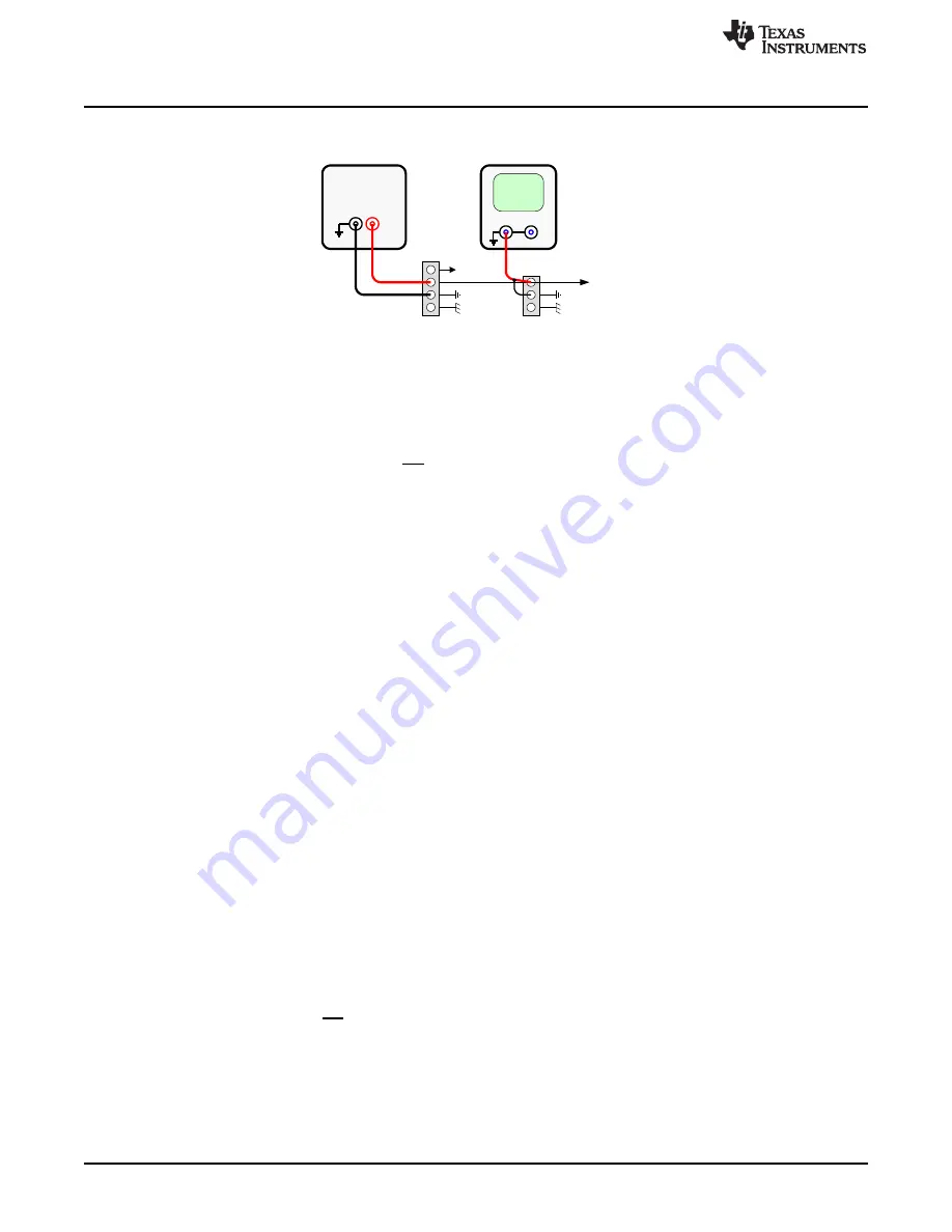
Figure 3. Example for Stimulus and Probe Points with JMP4 and JMP14

Figure 3

gives an example for entering a data signal into the driver section of the transceiver. The signal

output of the generator is adjusted to match the device V

CC

power supply requirements . The generator’s

ground terminal is connected with pin 3, and the signal output terminal with pin 2 of JMP4. The data signal
is measured through an oscilloscope with its signal input connected to pin 1 and its ground wire connected
to pin 2 of JMP14.

The same setup applies to the DE and RE inputs through their corresponding headers JMP2 and JMP12
and JMP3 and JMP13. JMP1 however, must not receive a signal stimulus. Like JMP11, it represents the
receiver output, R, of the half-duplex RS-485 device.

Instead of using signal generators, the EVM can directly interface to the micro controller I/O. Then the
non-assembled 50-

resistors are of no concern. However, for proper operation, it must be assured that

the high-level input voltage V

IH

2 V and the low-level input voltage V

IL

0.8 V.

3

Powering Up the EVM and Taking Measurements

The generally recommended procedure for taking measurements is listed:

1. Install the required ground connections.

2. Connect the oscilloscope with the respective probe points you want to measure.

3. Adjust the power-supply to match the V

CC

requirements of the selected RS-485 device.

4. Adjust the generator outputs for a maximum output signal level, based on the V

CC

requirements of your

selected RS-485 device, or check the logic switching levels of the controller I/O.

5. Connect the power supply conductor with pin 3 of TB1 and observe the blue LED (D1) turning on.

6. Connect signal conductors from the controller or the generator with their corresponding EVM inputs at

JMP2 to JMP4.

7. Logic high at the receiver output, R, will turn on the red LED (D3), and logic high at the driver input, D,

turns on the green LED (D2). If D is left open, an internal 100-k

pull-up resistor provides logic high

instead. However, due to the small input current, D2 will remain off.

3.1

Measurement Examples

Each of the following measurement examples show the equivalent circuit diagram and the corresponding
EVM setup. Only the measurement relevant headers and terminal blocks are shown, and not necessarily
at their exact location on the EVM.

1. Standard Transceiver Configuration

Normal transceiver operation requires both the driver and the receiver sections being active. Therefore,
the receiver enable pin (RE) must be at logic low potential and the driver enable pin (DE) at logic high.

Transmit data entering at the D-input terminal appear as the differential output voltage (V

OD

= V

A

– V

B

)

on the bus wires, A and B. Via the active receiver, it is possible to sense the data traffic in transmit
direction.

4

RS-485 Half-Duplex Evaluation Module

SLLU173A – October 2012 – Revised November 2012

Submit Documentation Feedback

Copyright © 2012, Texas Instruments Incorporated

Summary of Contents for RS485-HF-DPLX-EVM

Page 1: ...gures 1 RS 485 Half Duplex EVM Schematic 3 2 Bridging DUT_GND with EARTH_GND 3 3 Example for Stimulus and Probe Points with JMP4 and JMP14 4 4 Transceiver Configuration for Normal Operation 5 5 RS 485 Half Duplex EVM Setup for Normal Transceiver Operation 5 6 Configuration for Maximum Loading 6 7 RS 485 Half Duplex EVM Setup for Maximum Loading 6 8 RS 485 Half Duplex EVM Configurations Left as Rec...

Page 2: ...VM See http www ti com tool rs485 hf dplx evm for more information 2 EVM Setup and Precautions Figure 1 shows the schematic of the EVM The EVM board has headers labeled from JMP1 to JMP14 JMP5 is omitted and two 3 pin terminal blocks labeled TB1 and TB2 These headers support device evaluation for a wide range of system configurations NOTE The examples in this document show a 3 3 V signal generator...

Page 3: ...LUE LED Diode 1 2 C5 0 1uF R14 1k Ohms JMP7 Header 4x1 1 2 3 4 R1 1k Ohms JMP13 Header 3x1 1 2 3 JMP1 Header 4x1 1 2 3 4 JMP6 Header 4x1 1 2 3 4 TB1 3PIN_TERMINAL_BLOCK 1 2 3 JMP11 Header 3x1 1 2 3 R9 0 Ohm C8 UNINSTALLED R8 0 Ohm R10 0 Ohm www ti com EVM Setup and Precautions Figure 1 RS 485 Half Duplex EVM Schematic For the first measurements ignore the common mode simulation and connect EARTH t...

Page 4: ... 2 Connect the oscilloscope with the respective probe points you want to measure 3 Adjust the power supply to match the VCC requirements of the selected RS 485 device 4 Adjust the generator outputs for a maximum output signal level based on the VCC requirements of your selected RS 485 device or check the logic switching levels of the controller I O 5 Connect the power supply conductor with pin 3 o...

Page 5: ...P2 and the high potential for DE through a wire bridge from pin 2 to pin 1 at JMP3 Data from the signal generator enter the board at pin 2 and pin 3 of JMP4 This data is measured via channel 1 which is connected to pin 1 and pin 2 of JMP14 Channel 2 measures the receive data at JMP11 and channels 3 and 4 the bus voltages VA and VB at JMP6 2 Operation Under Maximum Load EIA 485 RS 485 specifies thr...

Page 6: ...d to be implemented to reflect maximum load conditions replace R5 120 Ω default with 60 Ω replace R8 and R9 0 Ω default with 375 Ω connect pin 2 of JMP7 with pin 1 and pin 3 with pin 4 replace the previous wire bridge at TB1 with a second power supply unit PSU2 and connect the ground terminals of both PSU1 and PSU2 with a wire bridge as shown in Figure 7 Figure 7 RS 485 Half Duplex EVM Setup for M...

Page 7: ... RE DE 1 JMP14 2 3 1 2 3 TB1 GND EARTH VCC 1 2 3 TB2 B A 3 3V 3 3V www ti com Powering Up the EVM and Taking Measurements Figure 8 RS 485 Half Duplex EVM Configurations Left as Receiver EVM Right as Transmitter EVM Figure 9 Top View of RS 485 Half Duplex EVM 7 SLLU173A October 2012 Revised November 2012 RS 485 Half Duplex Evaluation Module Submit Documentation Feedback Copyright 2012 Texas Instrum...

Page 8: ...485 Half Duplex EVM For detailed information on the device parameters see the data sheet of the selected device at www ti com 8 RS 485 Half Duplex Evaluation Module SLLU173A October 2012 Revised November 2012 Submit Documentation Feedback Copyright 2012 Texas Instruments Incorporated ...

Page 9: ...ency energy and has not been tested for compliance with the limits of computing devices pursuant to part 15 of FCC or ICES 003 rules which are designed to provide reasonable protection against radio frequency interference Operation of the equipment may cause interference with radio communications in which case the user at his own expense will be required to take whatever measures may be required t...

Page 10: ... its gain should be so chosen that the equivalent isotropically radiated power e i r p is not more than that necessary for successful communication This radio transmitter has been approved by Industry Canada to operate with the antenna types listed in the user guide with the maximum permissible gain and required antenna impedance for each antenna type indicated Antenna types not included in this l...

Page 11: ...er you obtained the Technical Regulations Conformity Certification as provided in Radio Law of Japan with respect to this product Also please do not transfer this product unless you give the same notice above to the transferee Please note that if you could not follow the instructions above you will be subject to penalties of Radio Law of Japan Texas Instruments Japan Limited address 24 1 Nishi Shi...

Page 12: ... property damage personal injury or death If there are questions concerning these ratings please contact a TI field representative prior to connecting interface electronics including input power and intended loads Any loads applied outside of the specified output range may result in unintended and or inaccurate operation and or possible permanent damage to the EVM and or interface electronics Plea...

Page 13: ...regulatory and safety related requirements concerning its products and any use of TI components in its applications notwithstanding any applications related information or support that may be provided by TI Buyer represents and agrees that it has all the necessary expertise to create and implement safeguards which anticipate dangerous consequences of failures monitor failures and their consequence...

Page 14: ...Mouser Electronics Authorized Distributor Click to View Pricing Inventory Delivery Lifecycle Information Texas Instruments RS485 HF DPLX EVM ...

Reviews: