Texas Instruments RF430F5978EVM User Manual Download Page 23

www.ti.com

Programming Hardware Interface

18.5 AP434R01 Hardware Connection for Programming With MSP FET Tool

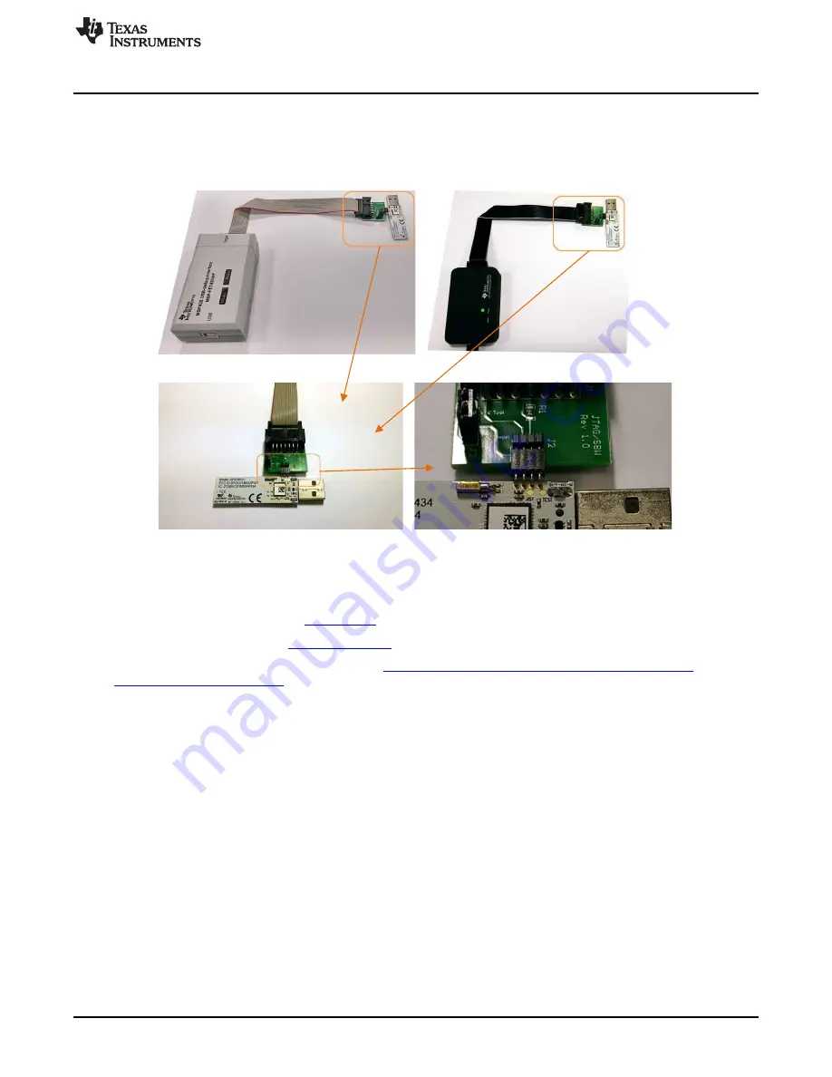
1. Connect the JTAG cable to the MSP430FETUIF or the MSP-FET tool and JTAG/SBW adapter.

2. Connect the 4-pin connector to the JTAG/SBW adapter.

3. Connect the 4-pin connector to AP434R01 SBW pins from AP434R01 bottom layer (see

Figure 22

).

Figure 22. Connect FET Tool to AP434R01 Module

19

Professional Software Development Tools

Code Composer Studio™ IDE (

CCSTUDIO

)

IAR Embedded Workbench (

IAR-KICKSTART

)

For more information, see the TI web site at

http://www.ti.com/lsds/ti/microcontrollers_16-bit_32-

bit/msp/tools_software.page

23

SLRU007 – July 2014

RF430F5978EVM User Guide

Submit Documentation Feedback

Copyright © 2014, Texas Instruments Incorporated

Summary of Contents for RF430F5978EVM

Page 1: ...als may be present on all devices In addition modules or peripherals may differ in their exact implementation between device families or may not be fully implemented on an individual device or device family Pin functions internal signal connections and operational parameters differ from device to device The user should consult the device specific data sheet for these details 1 SLRU007 July 2014 RF...

Page 2: ...F Wake Up Mode With UHF Response 11 11 LF Wake Up Mode Tab 12 12 LF Antenna Trimming Tab 14 13 Test Tab 15 14 AES Transponder User Interface 16 15 UHF Configuration Settings 19 16 Configuration Software for UHF block 19 17 RF430F5978EVM Hardware Description 20 18 Programming Hardware Interface 21 19 Professional Software Development Tools 23 20 Schematics 24 2 RF430F5978EVM User Guide SLRU007 July...

Page 3: ...stance within 5 cm relative to the 3D LF transponder using RSSI return signal strength indicator within a 4 m radius of the reader s LF trigger Protects sensitive data and prevents signal interference with the AES security coprocessor that allows data encryption for product authentication and secure access control Provides flexible customization at ultra low power with the programmable MSP430 core...

Page 4: ...l sequence the MRD2EVM LF transmitter sends a 64 bit wake pattern and as soon as the RF430F5978EVM board is within the supply range typically 2 m with the components in this kit but can reach up to 10 m with an LF power transmitter and detects a valid wake pattern then activates the microcontroller The microcontroller then measures the receive signal strength RSSI of all three axes on the 3D LF an...

Page 5: ...1 GUI Tabs Tab Name Contents and Functions 1 LF Wake Up Mode Demonstrate LF Wake Up Mode with UHF response 2 LF ANT Trimming LF Antenna Trimming function 3 Test Hardware Function test 4 AES Transponder AES Transponder function User Terminal 5 About Software version and User Guide of RF430F5978EVM Figure 3 RF430F5978EVM GUI 5 SLRU007 July 2014 RF430F5978EVM User Guide Submit Documentation Feedback ...

Page 6: ...or equivalent Battery requirements CR2032 UL recognized component battery Voltage 3 V Capacity 230 mAh typical data sheet numbers Minimum Capacity for 1 hour operation 5 mAh 7 Software Driver and Documentation The latest software driver and user guide are available at www ti com tool RF430F5978EVM 1 Download the RF430F5978EVM EXE installer file to the PC 2 The installer file includes software driv...

Page 7: ...CR2032 battery in the RF430F5978EVM module as shown in Figure 5 Figure 5 RF430F5978EVM Battery Assembly 2 Connect MRD2 reader and the AP434R01 access point to USB interfaces on the PC see Figure 6 Figure 6 RF430F5978EVM USB Connection 7 SLRU007 July 2014 RF430F5978EVM User Guide Submit Documentation Feedback Copyright 2014 Texas Instruments Incorporated ...

Page 8: ... driver 4 Install the AP434R01 UHF access point driver the AP434R01 Virtual COM Port driver The operating system should automatically detect the COM port driver for theAP434R01 If you are prompted for the driver the default installation location is C Program Files x86 RF430F5978EVM Driver Driver INF file RF_AP inf Follow the instructions of the operating system to install the driver 5 Set the powe...

Page 9: ...art the software RF430F5978EVM 2 Click Connect 3 Check if the Microreader and USB access point are available see Figure 8 Figure 8 RF430F5978EVM GUI Hardware Status 1 4 If MDR2 and USB Access point not available ensure that the MRD2 and AP434R01 access point are connected to the PC and then click Connect again 9 SLRU007 July 2014 RF430F5978EVM User Guide Submit Documentation Feedback Copyright 201...

Page 10: ...croreader and USB access point are available see Figure 9 Figure 9 RF430F5978EVM GUI Hardware Status 2 6 If both are available the software is ready to start the demo 10 RF430F5978EVM User Guide SLRU007 July 2014 Submit Documentation Feedback Copyright 2014 Texas Instruments Incorporated ...

Page 11: ...n LF wake pattern and can then receive the UHF response of the RF430F5978EVM module that receives the wake up signal see Figure 10 1 Click Wake up button to start the wake up sequence one time 2 Click Continuous wake up to initiate continuous mode approximately 2 s cycle time 3 Click Continuous wake up again to stop the continuous mode Figure 10 RF430F5978EVM Wakeup Mode Demo 1 11 SLRU007 July 201...

Page 12: ...Refer to the following description for more details Figure 11 RF430F5978EVM Wakeup Mode Demo 2 1 LF RSSI bars displays the different RSSI received signal strength indicator values of the 3D antenna red for x green for y blue for z The max value is 255 dBm The RSSI value of each RF430F5978 antenna axis depends on the RF430F5978 module position and orientation relative to the LF trigger MRD2 Continu...

Page 13: ... values vs input power levels at various frequencies The RF430F5978EVM power condition meets following regulations FCC 5 231 ETSSI 300 220 ETSSI 300 330 ETSSI 301 489 2 Link Quality Indicator LQI The Link Quality Indicator is a metric of the current quality of the received signal If PKTCTRL1 APPEND_STATUS is enabled the value is automatically added to the last byte appended after the payload The v...

Page 14: ...asured LF RSSI at MRD2 Trim Byte Display the trim byte 2 General Trimming function Target Frequency is at 134 2 kHz Checkbox Use median value The median value build out of 3 measurement values The trimming is more accurate but the process needs more time Get All RSSI Measure all LF RSSI values Auto Trimming All Internal cap trimming for all 3D Antennas Clear Trimming All Clear all Trimming setting...

Page 15: ... II Test Hardware test MRD2 Status Display Green indicates that the status of the USB connection to the MRD2 is OK The virtual COM port and firmware version are reported Red indicates that no MRD2 module is available Check the USB connection RF430F5978EVM Hardware test RF430F5978EVM Status Display Green indicates that RF430F5978EVM LF and UHF communication are OK The module name serial number and ...

Page 16: ... out complete Bank 3 and Bank 7 Pages from RF430F5978EVM module Read Selected Page Read out the selected page from RF430F5978EVM module Cancel reading Cancel the read operation 2 Transponder Bank 3 7 and Pages table Display the bank 3 7 and pages results 16 RF430F5978EVM User Guide SLRU007 July 2014 Submit Documentation Feedback Copyright 2014 Texas Instruments Incorporated ...

Page 17: ...uide scbu049 See Section 6 4 3 14 2 Predefined Commands Switch to wake up timing Special wake up timing Command 0x0D 01 12 83 0D 00 AA 03 E8 00 AA 00 FA 00 AA 02 8A 00 AA 27 10 32 SOFoff 170 µs SOFon 1000 µs toffLow 170 µs tonLow 250 µs toffHigh 170 µs tonHigh 650 µs EOFoff 170 µs EOFon 10000 µs Switch to default timing BLC Automotive Timing Command 0x0D 01 12 83 0D 00 AA 01 CC 00 AA 00 E6 00 AA 0...

Page 18: ...ceiver Read LF Page Read Transponder Bank and page Example Read Bank 3 Page 0 Send command 01 09 C8 A0 00 00 32 10 B0 00 0E FD Receive data 01 10 00 80 7E 00 00 00 00 00 00 00 00 00 B1 00 6B 2F 1B For detailed information see the RF430F59xx Family User s Guide SLAU378 in the section LF Passive Mode Downlink Protocols Read MRD2 serial number Read the serial number of Microreader 2 Send command 01 0...

Page 19: ...toflush false PA ramping false TX power 20 dBm 1 1 RF430F5978EVM power condition meets the FCC 5 231 requirements 16 Configuration Software for UHF block The RF430F5978 can be configured by using the SmartRF Studio software SWRC046 Because RF430F5978 selection is not available CC430 and CC1101 settings must be selected in SmartRF Studio The SmartRF Studio software is highly recommended for obtaini...

Page 20: ...dware Description www ti com 17 RF430F5978EVM Hardware Description Figure 16 RF430F5978EVM Module 20 RF430F5978EVM User Guide SLRU007 July 2014 Submit Documentation Feedback Copyright 2014 Texas Instruments Incorporated ...

Page 21: ...or AP434R01 module Figure 17 JTAG SBW Adapter Schematic Figure 18 4 Pin Connector 18 2 Required Equipment to Program the RF430F5978EVM and AP434R01 Modules The MSP FET430UIF or MSP FET Flash Emulation Tool http www ti com tool msp fet is needed to program the modules Figure 19 MSP FET430UIF Figure 20 MSP FET 21 SLRU007 July 2014 RF430F5978EVM User Guide Submit Documentation Feedback Copyright 2014...

Page 22: ...he RF430F5978EVM top layer and place the 4 pins in central position see Figure 21 Figure 21 Connect FET Tool to RF430F5978EVM Module 18 4 Access Point AP434R01 hardware based on MSP430F5509 MCU and CC1101 Transceiver Additional device specific information can be found on the MSP430 web site www ti com msp430 and on the Wireless Connectivity web site www ti com product cc1101 22 RF430F5978EVM User ...

Page 23: ...nnector to AP434R01 SBW pins from AP434R01 bottom layer see Figure 22 Figure 22 Connect FET Tool to AP434R01 Module 19 Professional Software Development Tools Code Composer Studio IDE CCSTUDIO IAR Embedded Workbench IAR KICKSTART For more information see the TI web site at http www ti com lsds ti microcontrollers_16 bit_32 bit msp tools_software page 23 SLRU007 July 2014 RF430F5978EVM User Guide S...

Page 24: ...78EVM Figure 23 RF430F5978EVM Photo Figure 24 RF430F5978EVM Module Schematic 20 2 LF 3D Antenna Figure 25 LF 3D Antenna Schematic 24 RF430F5978EVM User Guide SLRU007 July 2014 Submit Documentation Feedback Copyright 2014 Texas Instruments Incorporated ...

Page 25: ...m Schematics 20 3 APA434R01 Figure 26 APA434R01 Photo Figure 27 AP434R01 Module Schematic 25 SLRU007 July 2014 RF430F5978EVM User Guide Submit Documentation Feedback Copyright 2014 Texas Instruments Incorporated ...

Page 26: ...Photo Figure 29 MRD 2 Schematic For additional documents such as the Microreader Evaluation Kit description and user guide go to http www ti com tool mrd2evm 26 RF430F5978EVM User Guide SLRU007 July 2014 Submit Documentation Feedback Copyright 2014 Texas Instruments Incorporated ...

Page 27: ...ring the warranty period to the address designated by TI and that are determined by TI not to conform to such warranty If TI elects to repair or replace such EVM TI shall have a reasonable time to repair such EVM or provide replacements Repaired EVMs shall be warranted for the remainder of the original warranty period Replaced EVMs shall be warranted for a new full ninety 90 day warranty period 3 ...

Page 28: ... by Industry Canada to operate with the antenna types listed in the user guide with the maximum permissible gain and required antenna impedance for each antenna type indicated Antenna types not included in this list having a gain greater than the maximum gain indicated for that type are strictly prohibited for use with this device Concernant les EVMs avec antennes détachables Conformément à la rég...

Page 29: ... connecting any load to the EVM output If there is uncertainty as to the load specification please contact a TI field representative During normal operation even with the inputs and outputs kept within the specified allowable ranges some circuit components may have elevated case temperatures These components include but are not limited to linear regulators switching transistors pass transistors cu...

Page 30: ...F REMOVAL OR REINSTALLATION ANCILLARY COSTS TO THE PROCUREMENT OF SUBSTITUTE GOODS OR SERVICES RETESTING OUTSIDE COMPUTER TIME LABOR COSTS LOSS OF GOODWILL LOSS OF PROFITS LOSS OF SAVINGS LOSS OF USE LOSS OF DATA OR BUSINESS INTERRUPTION NO CLAIM SUIT OR ACTION SHALL BE BROUGHT AGAINST TI MORE THAN ONE YEAR AFTER THE RELATED CAUSE OF ACTION HAS OCCURRED 8 2 Specific Limitations IN NO EVENT SHALL T...

Page 31: ...esponsible for compliance with all legal regulatory and safety related requirements concerning its products and any use of TI components in its applications notwithstanding any applications related information or support that may be provided by TI Buyer represents and agrees that it has all the necessary expertise to create and implement safeguards which anticipate dangerous consequences of failur...

Reviews: