


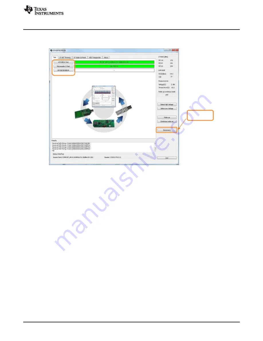
Disconnect or connect
hardware
1
Test Tab
13
Test Tab
shows the hardware Test tab. Refer to the following description for more details.
Figure 13. RF430F5978EVM Hardware Test Tab
AP434R01 Test
Hardware test "Access point"
Status Display:
Green indicates that the status of the USB connection to the access point is OK. The virtual COM port,
module serial number, frequency band, CW PA, and firmware version are reported.
Red indicates that no access point is available. Check the USB connection.
Microreader II Test
Hardware test "MRD2"
Status Display:
Green indicates that the status of the USB connection to the MRD2 is OK. The virtual COM port and
firmware version are reported.
Red indicates that no MRD2 module is available. Check the USB connection.
RF430F5978EVM
Hardware test "RF430F5978EVM"
Status Display:
Green indicates that RF430F5978EVM LF and UHF communication are OK. The module name, serial
number, and firmware version are reported.
Red indicates that communication with the RF430F5978EVM module is not possible.
Possible errors:
No Battery
Power Switch not in Battery mode
3D Antenna not connected
15
SLRU007 – July 2014
RF430F5978EVM User Guide
Copyright © 2014, Texas Instruments Incorporated