www.ti.com
Board Layout
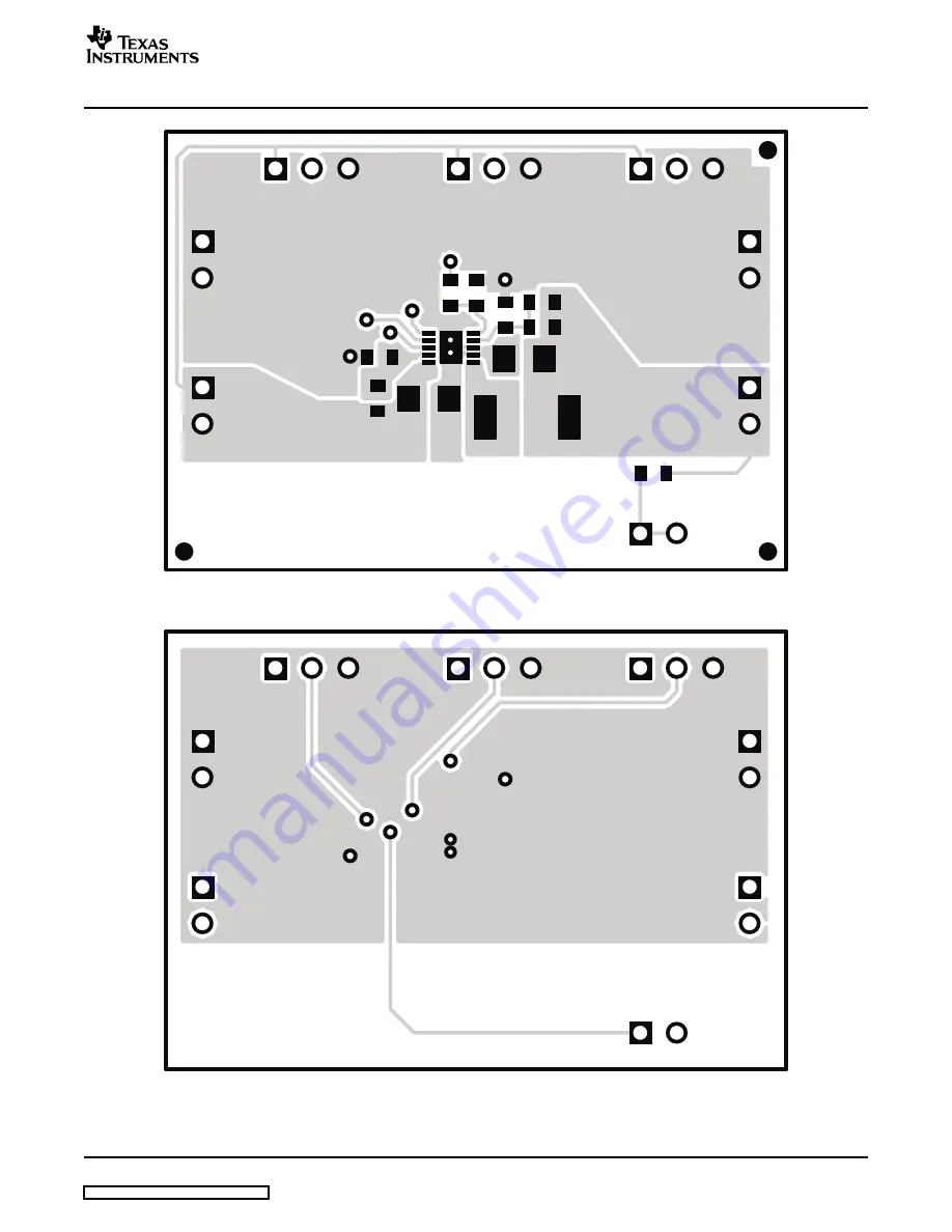
Figure 8. Top Layer Routing
Figure 9. Bottom Layer Routing
SLVU161 – May 2006
TPS62510EVM-168
7
Submit Documentation Feedback
Page 1: ...le Voltage 6 7 Assembly Layer 6 8 Top Layer Routing 7 9 Bottom Layer Routing 7 10 TPS62510EVM 168 Schematic 8 List of Tables 1 TPS62510EVM 168 Bill of Materials 8 The Texas Instruments TPS62510EVM 168 evaluation module EVM helps designers evaluate the operation and performance of the TPS62510 switching step down converter This high efficiency converter is targeted for portable devices where space ...
Page 2: ...t floating if unused For the EVM PG is tied to VOUT through a resistor This jumper toggles the operating mode of the IC between PFM PWM mode and Forced PWM mode Connect the shorting jumper to GND for PFM PWM operation connect the shorting jumper to VIN for Forced PWM operation Also by removing the jumper the MODE SYNC pin can also be connected to an external clock if it is desired to sync this EVM...
Page 3: ...put voltage adjusted between 0 6V VIN JP1 determines the mode for the part and the shorting jumper must be tied either to VIN for Forced PWM mode operation or to GND for PFM PWM mode operation JP2 is the enable for the switching converter and the shorting jumper must be tied to VIN to enable the part or GND to disable the part The EVM is not initially configured for OVT operation so the shorting j...
Page 4: ...s the 1 8V output voltage when the load current is pulsed between 1500mA and 150mA Vin 3 3Vdc SYNC Vin Blue Output Voltage 50mV DIV Green Output Current 500mA DIV 5µs DIV Figure 3 Output Voltage Figure 4 shows the 1 8V output voltage when the load current is pulsed between 150mA and 1500mA Vin 3 3Vdc SYNC Vin Blue Output Voltage 50mV DIV Green Output Current 500mA DIV 5µs DIV 4 TPS62510EVM 168 SLV...
Page 5: ...V Red Output Ripple Voltage 10mV DIV Green Inductor Current 500mA DIV 2us DIV Figure 5 Output Ripple Voltage The 1 8V output ripple voltage is shown in Figure 6 The image was taken with the output loaded to 1500mA and the input voltage set to 3 3Vdc Yellow Switchnode 2V DIV Blue Output Ripple Voltage 10mV DIV Green Inductor Current 200mA DIV 200ns DIV SLVU161 May 2006 TPS62510EVM 168 5 Submit Docu...
Page 6: ... Output Ripple Voltage This chapter provides the TPS62510 168 board layout and illustrations Figure 7 Figure 8 and Figure 9 show the board layout for the TPS63510 168 PWB Figure 7 Assembly Layer 6 TPS62510EVM 168 SLVU161 May 2006 Submit Documentation Feedback ...
Page 7: ...www ti com Board Layout Figure 8 Top Layer Routing Figure 9 Bottom Layer Routing SLVU161 May 2006 TPS62510EVM 168 7 Submit Documentation Feedback ...
Page 8: ...B TDK 5 J1 J5 Header 2 pin 100mil spacing 36 pin strip 0 100 2 PTC36SAAN Sullins 3 JP1 JP3 Header 3 pin 100mil spacing 36 pin strip 0 100 3 PTC36SAAN Sullins 1 L1 2 2µH Inductor SMT 2 3A 70mΩ 0 26 0 09 DO1608 222MLC Coilcraft 1 R1 402kΩ Resistor Chip 1 16W 1 0603 Std Std 1 R2 200kΩ Resistor Chip 1 16W 1 0603 Std Std 1 R3 0Ω Resistor Chip 1 16W 1 0603 Std Std 0 R4 Open Resistor Chip 1 16W 1 0603 1 ...
Page 9: ...struction of the product it is the user s responsibility to take any and all appropriate precautions with regard to electrostatic discharge EXCEPT TO THE EXTENT OF THE INDEMNITY SET FORTH ABOVE NEITHER PARTY SHALL BE LIABLE TO THE OTHER FOR ANY INDIRECT SPECIAL INCIDENTAL OR CONSEQUENTIAL DAMAGES TI currently deals with a variety of customers for products and therefore our arrangement with the use...
Page 10: ...If there is uncertainty as to the load specification please contact a TI field representative During normal operation some circuit components may have case temperatures greater than 50 C The EVM is designed to operate properly with certain components above 50 C as long as the input and output ranges are maintained These components include but are not limited to linear regulators switching transist...
Page 11: ...siness practice TI is not responsible or liable for any such statements TI products are not authorized for use in safety critical applications such as life support where a failure of the TI product would reasonably be expected to cause severe personal injury or death unless officers of the parties have executed an agreement specifically governing such use Buyers represent that they have all necess...