


Source clock 1
CM_CLKSEL_DOM
CLKSEL_CLK1
CM_FCLKEN_DOM.
EN_M1
CLK1
Clock
enable
Clock
disable
Clock
enable
Clock
disable
Clock source
switch
Source clock 2
CM_FCLKEN_DOM.
EN_M2
prcm-080
Public Version
PRCM Basic Programming Model
www.ti.com
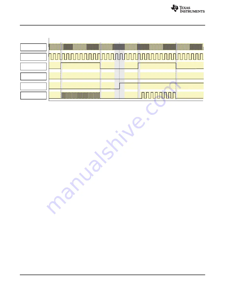
Figure 3-91. Functional Clock Switching
The following functional clocks require this switching sequence:
•
sys_clkout2
•
48M_FCLK (and all gated versions of it)
•
12M_FCLK (and all gated versions of it)
•
DSS_TV_CLK
•
GPTx_FCLK (with x = 1, 10, and 11)
•
GPTx_ALWON_FCLK (with x = 2 up to 9)
3.6.6.1.2 Enabling and Disabling the Interface Clocks
The flow chart in
shows the enable/disable sequence of the interface clock.
The first step before enabling an interface clock is to select the proper source clock using the
corresponding clock selection register (CM_CLKSEL_<domain>). This register allows selection of the
interconnect frequency (L3_ICLK, L4_ICLK) from among several divider ratios.
The interface clock is enabled or disabled by writing the dedicated bit in the CM_ICLKEN_<domain>
register. This bit has a direct effect on the clock activity:
•
The interface clock is turned on if the bit is enabled and the clock is not yet active.
•
The interface clock is turned off if the bit is disabled and the clock is not required by any other module.
The interface clock can be automatically enabled or disabled by the PRCM module, based on hardware
conditions. This automatic clock activity control mode is enabled by writing the corresponding bit in the
CM_AUTOIDLE_<domain > register. It takes effect only if the interface clock is enabled (the
corresponding bit in the CM_ICLKEN_<domain > is set to 1).
The hardware conditions for automatic gating (deactivation) of the clock are as follows:
•
The module activity; that is, the module is inactive.
•
The domain activity; that is, all modules in the domain are inactive.
The software can read the idle status register CM_IDLESTAT_<domain> at any time to know whether the
module is accessible. A module is inaccessible if its idle status bit is set. Accessing an idle module
generates an error (if the interface clock is still running) or a time-out (if the interface clock is cut).
426
Power, Reset, and Clock Management
SWPU177N – December 2009 – Revised November 2010
Copyright © 2009–2010, Texas Instruments Incorporated