


Public Version
www.ti.com
PRCM Functional Description
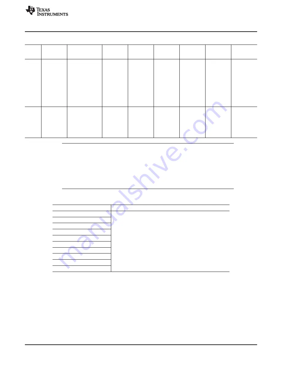
Table 3-82. VDD2 Voltage Domain Dependencies (continued)
VDD2
Power
DPLL State
sys_clk
Software
VDD1
VDD3
VDD4
VDD5
Domain Domains
Control
State
State
Retenti
Software
All DPLLs are in
No longer
AUTO_SLEE
ON or
ON or
ON or
Retention
on
controlled
Stop mode.
required
P = 0
retention
Overdriven
retention
power
AUTO_RET =
domains of
1
VDD1 are in
AUTO_OFF =
inactive,
0
retention or
off state and
of VDD2 are
in retention or
off state.
Off
Software
All DPLLs are in
No longer
AUTO_SLEE
Off
SLEEP
Off
Off
controllable
Stop mode.
required
P = 0
power
AUTO_RET =
domains of
0
VDD1 and
AUTO_OFF =
VDD2 are in
1
off state.
NOTE:
•
In voltage domain SLEEP state, the current load decreases because of reduced activity
level; however, the voltage level remains that of on state.
•
In voltage domain overdriven state, the domain voltage is raised above the nominal
operating voltage to boost performance; however, power consumption also increases.
•
AUTO_SLEEP, AUTO_RET and AUTO_OFF, in the Software Control column, refer to
the
[0] AUTO_SLEEP,
[1] AUTO_RET and
[2] AUTO_OFF bits.
Table 3-83. Remaining Voltage Domain Dependencies
Voltage
Condition
VDDS
External memory I/Os
VDDADAC
VDDPLL
VDDPLL_PER
CSIB
No dependency with other device voltages
DSI
CSIPHY2
SIM
MMC_VDDS
3.5.6.4
Voltage-Control Architecture
The PRM is split over several blocks that manage the different voltage sources.
•
VDD1 and VDD2 voltages are managed by multiple control sources:
–
Automatic voltage adjustment (for optimal performance at an OPP) and software-requested voltage
scaling (for OPP change) are managed by two SmartReflex voltage control modules connected to
two voltage processor modules. They generate voltage-adjustment commands based on the
desired and current performance levels of the device. These commands are sent to the external
power IC through a voltage controller and a dedicated I
2
C interface.
–
Direct software control of VDD1 and VDD2 is also possible by writing to the registers of the voltage
controller, which then sends the voltage commands to the power IC through the dedicated I
2
C
377
SWPU177N – December 2009 – Revised November 2010
Power, Reset, and Clock Management
Copyright © 2009–2010, Texas Instruments Incorporated


