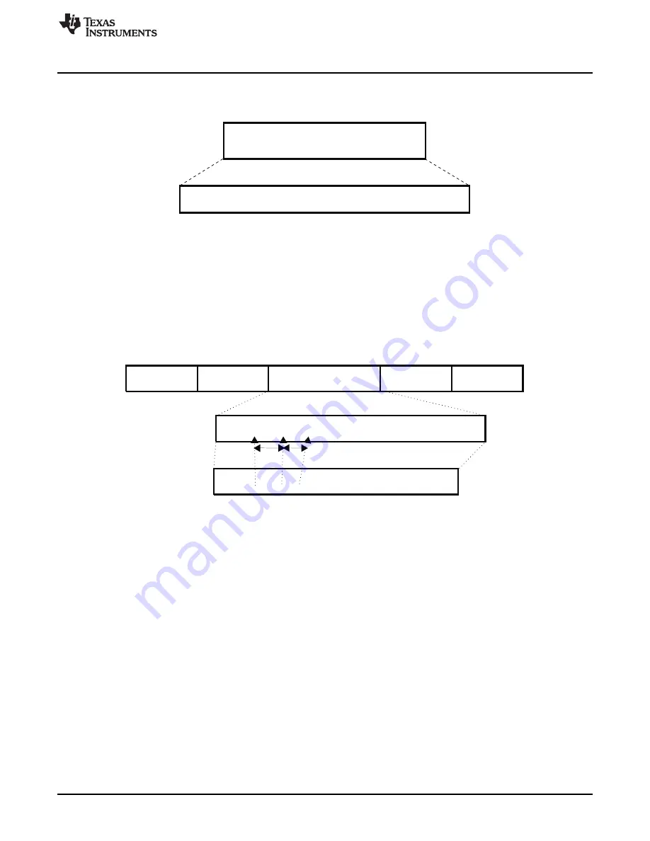
FIFO data
Free format
M * 8 bits
uart-009
Start flag
Frame data
CRC-16
Stop flag
FIFO data
..............01111111111110........................................................
Start flags
xn
Bit-stuffing
.............0111110111110110........................................................
5x1
5x1
uart-010
Public Version
www.ti.com
UART/IrDA/CIR Environment
Figure 19-9. SIR Free Format Mode
In the SIR free format mode, the MPU software must construct (that is, encode and decode) the entire
FIFO data packet.
19.2.5.2.3 MIR Mode
In MIR mode, data is transferred between the MPU and the peripheral devices at 0.576 or 1.152M bits/s
speed. A MIR transmit frame starts with start flags (at least two), followed by a frame data, CRC-16, and
ends with a stop flag (see
Figure 19-10. MIR Transmit Frame Format
On transmit, the MIR state-machine attaches start flags, CRC-16, and stop flags, as in SIR mode. All
fields are transmitted least-significant bit (LSB) of each byte first.
Contrary to SIR mode:
•
The state-machine looks for consecutive 1s in the frame data and automatically inserts 0 after five
consecutive 1s (this is called bit-stuffing).
•
0x7E is used for both start and stop flags (unambiguously, not data, because of bit-stuffing).
•
Abort sequence requires a minimum of seven consecutive 1s (unambiguously, not data, because of bit
stuffing).
•
Back-to-back frames are allowed with three or more stop flags in between. If two consecutive frames
are not back to back, the gap between the last stop flag of the first frame and the start flag of the
second frame must be separated by at least seven bit durations.
On receive, the MIR receive state-machine recovers the receive clock, removes the start flags, destuffs
the incoming data, and determines the frame boundary with reception of the stop flag. The state-machine
also checks for errors, such as frame abort, CRC error, and frame-length error. At the end of a frame
reception, the MPU reads the line status register (UART3.
) to detect possible errors of the
received frame.
Data can be transferred both ways by the module, but when the device is transmitting, the IR RX circuitry
is automatically disabled by hardware.
2879
SWPU177N – December 2009 – Revised November 2010
UART/IrDA/CIR
Copyright © 2009–2010, Texas Instruments Incorporated


