background image


22      

SNAU049A


LMK2430/33/34 Family   

November 2013 

Copyright © 2013, Texas Instruments Incorporated 

www.ti.com


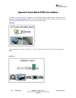
Appendix E: Quick Start for EVM Communications 


Codeloader is the software used to communicate with the EVM (Please download the latest version from TI.com - 

http://www.ti.com/tool/codeloader

). This EVM can be controlled through the uWire interface on board. There are 

two options in communicating with the uWire interface from the computer. 

 
OPTION 1 


Open Codeloader.exe 

 Click “Select Device” 

 Click “Port Setup” tab 

 Click “LPT” (in Communication 

Mode) 


OPTION 2 


Summary of Contents for LMX2430

Page 1: ...LMX2430 33 34 Evaluation Board User s Guide November 2013 SNAU049A ...

Page 2: ...2 SNAU049A LMK2430 33 34 Family November 2013 Copyright 2013 Texas Instruments Incorporated www ti com LMX2430 33 34 Evaluation Board Instructions ...

Page 3: ...F CONTENTS EQUIPMENT 4 BASIC OPERATION 5 LMX243X BOARD INFORMATION 7 LMX2430 MEASUREMENTS 8 LMX2433 MEASUREMENTS 10 LMX2434 MEASUREMENTS 12 APPENDIX A SCHEMATIC 14 APPENDIX B BUILD DIAGRAM 15 APPENDIX C FABRICATION AND ASSEMBLY 20 APPENDIX D BILL OF MATERIALS 20 APPENDIX E QUICK START FOR EVM COMMUNICATIONS 22 ...

Page 4: ... these evaluation board instructions Phase Noise Spectrum Analyzer For measuring phase noise an Agilent E5052A is recommended An Agilent E4445A PSA Spectrum Analyzer with the Phase Noise option is also usable although the architecture of the E5052A is superior for phase noise measurements At frequencies less than 100 MHz the local oscillator noise of the PSA is too high and measurements will be of...

Page 5: ...a low noise 5 0 V power supply to the Vcc connector located at the top left of the board 3 Please see Appendix C for quick start on interfacing the board Connect PC to the uWire header 5 0 V Power Supply Vcc Signal Generator SMA Cable SMA Cable OSCin 10 MHz 1 2 Laptop or PC Laptop or PC 3 Please see Appendix D for interface info Please see Appendix D for interface info 4 Run CodeLoader4 exe 5 Sele...

Page 6: ...corporated www ti com 6 On the RF PLL Tab make sure Reference Oscillator is 10 MHz and output frequency is set to within the range of the VCO on the board Press Enter after making a change 7 To program the settings into the device Click Keyboard Controls Load Device or Press CTRL L ...

Page 7: ... 22 12 Phase Detector Frequency MHz 1 1 1 OSCin Frequency MHz 100 100 100 Loop Bandwidth kHz 27 9 31 1 41 2 Phase Margin deg 56 8 59 6 58 4 Gamma 0 57 0 90 0 87 T3 T1 Ratio 220 8 177 1 213 9 C1_LF nF 0 18 0 27 0 1 C2_LF nF 6 8 10 3 9 C3_LF nF 1 1 1 C4_LF nF Open Open Open R2_LF Kohm 2 2 1 8 3 3 R3_LF Kohm 0 82 0 82 0 68 R4_LF Kohm 0 0 0 Closed Loop Transfer Function 60 40 20 0 20 40 60 80 1 E 02 1...

Page 8: ...8 SNAU049A LMK2430 33 34 Family November 2013 Copyright 2013 Texas Instruments Incorporated www ti com LMX2430 Measurements ...

Page 9: ... SNAU049A 9 Copyright 2013 Texas Instruments Incorporated www ti com Spur at 1600 MHz VCO frequency is 79 9 dBc Spur at 1650 MHz VCO frequency is 79 5 dBc Note that this spur is not symmetrical Spur at 1675 MHz VCO frequency is 77 6 dBc ...

Page 10: ...10 SNAU049A LMK2430 33 34 Family November 2013 Copyright 2013 Texas Instruments Incorporated www ti com LMX2433 Measurements ...

Page 11: ...9A 11 Copyright 2013 Texas Instruments Incorporated www ti com Spur at 3200 MHz VCO frequency is below the noise floor Spur at 3300 MHz VCO frequency is 83 4 dBc Spur at 3400 MHz VCO frequency is 83 6 dBc Note that this spur is not symmetrical ...

Page 12: ...12 SNAU049A LMK2430 33 34 Family November 2013 Copyright 2013 Texas Instruments Incorporated www ti com LMX2434 Measurements ...

Page 13: ...013 LMK2430 33 34 Family SNAU049A 13 Copyright 2013 Texas Instruments Incorporated www ti com Spur at 4690 MHz VCO is 77 1 dBc Spur at 4790 MHz VCO frequency is 79 1 dBc Spur at 4890 MHz VCO frequency is 76 5 dBc ...

Page 14: ... GND 3 GND 4 GND 5 MOD 6 GND 7 GND 8 GND 9 RFout 10 GND 11 GND 12 GND 13 Vcc 14 GND 15 GND 16 U3 VCO GND 1 Vt 2 GND 3 GND 4 GND 5 MOD 6 GND 7 GND 8 GND 9 RFout 10 GND 11 GND 12 GND 13 Vcc 14 GND 15 GND 16 U2 VCO R4_IF 0 ohm C4_IF Open R9 Open R11 Open R8 Open R10 Open R34 3 3 ohm R20 3 3 ohm R25 3 3 ohm R4_RF 0 ohm C4_RF Open Vcc_PLL 1 2 3 4 5 6 7 8 POWER HEADER_2X4 Vcc_AMP Vcc_RF Vcc_IF Vcc SMA I...

Page 15: ...November 2013 LMK2430 33 34 Family SNAU049A 15 Copyright 2013 Texas Instruments Incorporated www ti com Appendix B Build Diagram ...

Page 16: ...16 SNAU049A LMK2430 33 34 Family November 2013 Copyright 2013 Texas Instruments Incorporated www ti com Top Layer ...

Page 17: ...November 2013 LMK2430 33 34 Family SNAU049A 17 Copyright 2013 Texas Instruments Incorporated www ti com GND Layer ...

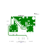
Page 18: ...18 SNAU049A LMK2430 33 34 Family November 2013 Copyright 2013 Texas Instruments Incorporated www ti com POWER Layer ...

Page 19: ...November 2013 LMK2430 33 34 Family SNAU049A 19 Copyright 2013 Texas Instruments Incorporated www ti com Bottom Copper ...

Page 20: ...Layers 4 Board Thickness 0 062 Copper Weight 1 oz Finished Finish Immersion Gold Solder Mask Color Green Gloss Testing 100 Electrical Testing Name K Tand RO4003 16 mil 3 38 0 0022 RO4003 r 3 38 CONTROLLED THICKNESS of 16 mils thick Top Copper 1oz thick LMX2434 GTL GND Layer LMX2434 G1 FR4 r 4 6 mils thick but thinner is preferable POWER Layer LMX2434 G2 FR4 mils thick Bottom Copper Thermal relief ...

Page 21: ... OSCin RFout Vcc Op AMP Texas Instruments LM6211 1 U5 LDO Texas Instruments LP5900 2 5 1 U4 Standoff SPC Technology SPCS 6 4 Place in 4 holes in corners of board Jumper Sullins Electronics Corp S9000 4 Place on the POWER header Open Open Capacitors Open Open 6 C4_RF C6 C7 C11 Ca_LF C2pRF Open Resistors Open Open 9 R1bRF R2pRF R8 R9 R10 R11 R14 R15 R30 Open IF Loop Filter 10 C1_IF C2_IF C2pIF C3_IF...

Page 22: ...re used to communicate with the EVM Please download the latest version from TI com http www ti com tool codeloader This EVM can be controlled through the uWire interface on board There are two options in communicating with the uWire interface from the computer OPTION 1 Open Codeloader exe Click Select Device Click Port Setup tab Click LPT in Communication Mode OPTION 2 ...

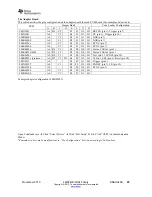
Page 23: ... F1 G1 H1 SYNC pin 7 LMK02000 A0 C1 E5 F1 G1 H1 SYNC pin 7 LMK0480x A0 B2 C3 E5 F0 G0 H1 Status_CLKin1 pin 3 LMK04816 4906 A0 B2 C3 E5 F0 G0 H1 Status_CLKin1 pin 3 LMK01801 A0 B4 C5 E2 F0 G0 H1 Test pin 3 SYNC0 pin 10 LMK0482x prelease A0 B5 C3 D2 E4 F0 G0 H1 CLKin1_SEL pin 6 Reset pin 10 LMX2531 A0 E5 F2 G1 H2 Trigger pin 1 LMX2485 7 A0 C1 E5 F2 G1 H0 ENOSC pin 7 CE pin 10 LMK03200 A0 E5 F0 G0 H1...

Page 24: ...ring the warranty period to the address designated by TI and that are determined by TI not to conform to such warranty If TI elects to repair or replace such EVM TI shall have a reasonable time to repair such EVM or provide replacements Repaired EVMs shall be warranted for the remainder of the original warranty period Replaced EVMs shall be warranted for a new full ninety 90 day warranty period 3 ...

Page 25: ... by Industry Canada to operate with the antenna types listed in the user guide with the maximum permissible gain and required antenna impedance for each antenna type indicated Antenna types not included in this list having a gain greater than the maximum gain indicated for that type are strictly prohibited for use with this device Concernant les EVMs avec antennes détachables Conformément à la rég...

Page 26: ... connecting any load to the EVM output If there is uncertainty as to the load specification please contact a TI field representative During normal operation even with the inputs and outputs kept within the specified allowable ranges some circuit components may have elevated case temperatures These components include but are not limited to linear regulators switching transistors pass transistors cu...

Page 27: ...F REMOVAL OR REINSTALLATION ANCILLARY COSTS TO THE PROCUREMENT OF SUBSTITUTE GOODS OR SERVICES RETESTING OUTSIDE COMPUTER TIME LABOR COSTS LOSS OF GOODWILL LOSS OF PROFITS LOSS OF SAVINGS LOSS OF USE LOSS OF DATA OR BUSINESS INTERRUPTION NO CLAIM SUIT OR ACTION SHALL BE BROUGHT AGAINST TI MORE THAN ONE YEAR AFTER THE RELATED CAUSE OF ACTION HAS OCCURRED 8 2 Specific Limitations IN NO EVENT SHALL T...

Page 28: ...esponsible for compliance with all legal regulatory and safety related requirements concerning its products and any use of TI components in its applications notwithstanding any applications related information or support that may be provided by TI Buyer represents and agrees that it has all the necessary expertise to create and implement safeguards which anticipate dangerous consequences of failur...

Page 29: ...Mouser Electronics Authorized Distributor Click to View Pricing Inventory Delivery Lifecycle Information Texas Instruments LMX2430EVAL NOPB LMX2434EVAL LMX2434EVAL NOPB ...

Reviews: