background image

Powering and Loading Considerations

www.ti.com

3

Powering and Loading Considerations

Read this entire section prior to attempting to power the evaluation board.

3.1

Quick Start Procedure

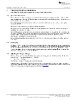
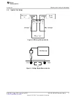
Step 1: Set the bench power supply current limit to 3A. Set the power supply voltage to 4V. Turn off the
power supply output. Connect the power supply to the LMR10530 demo board. Positive connection to V

IN

and negative connection to GND.

Step 2: Connect a load, as high as 3A, to the V

OUT

terminal. Positive connection to V

OUT

and negative

connection to GND.

Step 3: The EN pin should be left open for normal operation.

Step 4: Turn on the bench power supply with no load applied to the LMR10530. The V

OUT

would be in

regulation at a nominal 1.2V output.

Step 5: Slowly increase the load while monitoring the output voltage, V

OUT

should remain in regulation as

the load is increased up to 3 Amps. The LMR10530 is designed to skip some pulses at very light loads to
maintain output voltage regulation. Depending on load levels, the circuit may operate in either
discontinuous or continuous conduction mode.

Step 6: Slowly sweep the input voltage from 3 to 5.5V, V

OUT

should remain in regulation with a nominal

1.2V output.

3.2

Starting Up

By default, VINC is connected to V

IN

through a low pass filter to remove any high frequency noise present

at the input. EN is connected to VINC through a 100k

resistor. A separate logic signal at the EN terminal

can be used, if startup and shutdown need to be controlled. The EN pin is tied to V

IN

to simplify start-up.

The pull-up resistor allows the power supply design engineer to toggle EN independently, if desired, and
observe the start-up behavior of the LMR10530.

3.3

Adjusting the Output Voltage

The output voltage is set using the following equation where R

fbb

is connected between the FB pin and

GND, and R

fbt

is connected between V

OUT

and FB.

V

OUT

= V

FB

(1 + (R

fbt

/R

fbb

))

(1)

The feedback voltage VFB is regulated at 0.60V typically.

Adjusting the output voltage will affect the performance of the LMR10530. In addition, output capacitors
might not be rated for the new output voltage. For more information, see LMR10530 SIMPLE SWITCHER
5.5Vin, 3.0A Step-Down Voltage Regulator in WSON-10 
(

SNVS814

).

2

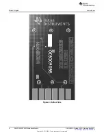
AN-2280 LMR10530 Evaluation Module

SNVU192A – October 2012 – Revised April 2013

Submit Documentation Feedback

Copyright © 2012–2013, Texas Instruments Incorporated

Summary of Contents for LMR10530

Page 1: ...tly underneath the device This user s guide contains the evaluation module schematic a quick setup procedure and a Bill of Materials BOM For complete circuit design information see LMR10530 SIMPLE SWITCHER 5 5Vin 3 0A Step Down Voltage Regulator in WSON 10 SNVS814 The module has a Cff capacitor footprint reserved for applications requiring higher VOUT The Cff cap also helps to minimize the output ...

Page 2: ... Step 6 Slowly sweep the input voltage from 3 to 5 5V VOUT should remain in regulation with a nominal 1 2V output 3 2 Starting Up By default VINC is connected to VIN through a low pass filter to remove any high frequency noise present at the input EN is connected to VINC through a 100kΩ resistor A separate logic signal at the EN terminal can be used if startup and shutdown need to be controlled Th...

Page 3: ...iderations 3 4 Typical Test Setup Figure 2 Efficiency Measurements Figure 3 Voltage Ripple Measurements 3 SNVU192A October 2012 Revised April 2013 AN 2280 LMR10530 Evaluation Module Submit Documentation Feedback Copyright 2012 2013 Texas Instruments Incorporated ...

Page 4: ... 3 4 5 6 A B C D E F VIN VOUT GND Powering and Loading Considerations www ti com Figure 4 Edge Connector Schematic 4 AN 2280 LMR10530 Evaluation Module SNVU192A October 2012 Revised April 2013 Submit Documentation Feedback Copyright 2012 2013 Texas Instruments Incorporated ...

Page 5: ...com Board Images 4 Board Images Figure 5 Top Side 5 SNVU192A October 2012 Revised April 2013 AN 2280 LMR10530 Evaluation Module Submit Documentation Feedback Copyright 2012 2013 Texas Instruments Incorporated ...

Page 6: ...oard Images www ti com Figure 6 Bottom Side 6 AN 2280 LMR10530 Evaluation Module SNVU192A October 2012 Revised April 2013 Submit Documentation Feedback Copyright 2012 2013 Texas Instruments Incorporated ...

Page 7: ...2V Vin 5 5V VOUT 1 2V 500 mV Div 1V Div 100 Ps DIV VIN 5 5V 2A Div IOUT 3A www ti com Typical Performance Characteristics 5 Typical Performance Characteristics Efficiency vs Load Current VOUT 1 2V Startup Steady state CCM Mode Steady state DCM Mode VIN 3V IOUT 3A VIN 5 5V IOUT 0 025A Load Transient VIN 5 5V IOUT 0 3A to 3A 7 SNVU192A October 2012 Revised April 2013 AN 2280 LMR10530 Evaluation Modu...

Page 8: ...CMS01 Toshiba Rfbt 2 00kΩ 1 1 8W 0603 CRCW06032K00FKEA Vishay Rfbb 2 00kΩ 1 1 8W 0603 CRCW06032K00FKEA Vishay Rinc 10 0Ω 1 1 8W 0603 CRCW060310R0FKEA Vishay Ren 100kΩ 1 1 8W 0603 CRCW0603100KFKEA Vishay VIN Test Point Loop 5010 Keystone SW Test Point Loop 5012 Keystone GND Test Point Loop 5011 Keystone GND Test Point Loop 5011 Keystone VOUT Test Point Loop 5013 Keystone EN Test Point Loop 5014 Key...

Page 9: ...ayout 7 Layout Figure 7 Top Copper Figure 8 Top Overlay 9 SNVU192A October 2012 Revised April 2013 AN 2280 LMR10530 Evaluation Module Submit Documentation Feedback Copyright 2012 2013 Texas Instruments Incorporated ...

Page 10: ...com Figure 9 Internal Plane 1 Figure 10 Internal Plane 2 10 AN 2280 LMR10530 Evaluation Module SNVU192A October 2012 Revised April 2013 Submit Documentation Feedback Copyright 2012 2013 Texas Instruments Incorporated ...

Page 11: ...ayout Figure 11 Bottom Overlay Figure 12 Bottom Copper 11 SNVU192A October 2012 Revised April 2013 AN 2280 LMR10530 Evaluation Module Submit Documentation Feedback Copyright 2012 2013 Texas Instruments Incorporated ...

Page 12: ...esponsible for compliance with all legal regulatory and safety related requirements concerning its products and any use of TI components in its applications notwithstanding any applications related information or support that may be provided by TI Buyer represents and agrees that it has all the necessary expertise to create and implement safeguards which anticipate dangerous consequences of failur...

Page 13: ...Mouser Electronics Authorized Distributor Click to View Pricing Inventory Delivery Lifecycle Information Texas Instruments LMR10530YSDEVM NOPB ...

Reviews: