N
Copyright © 1999, 2000 National Semiconductor
www.national.com
- 1 -
November 2000
Evaluation Board Instruction Manual
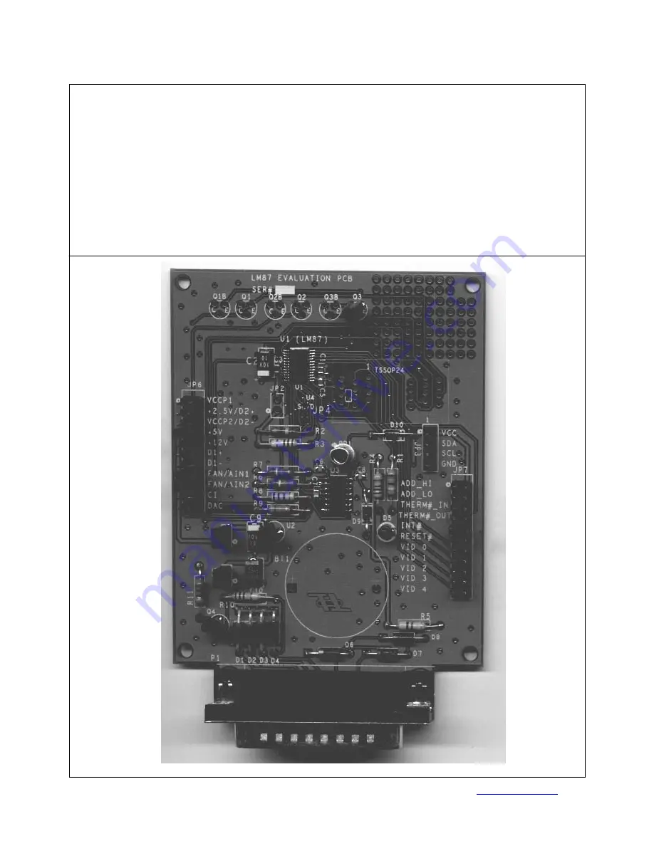
LM87Serial Interface System Hardware Monitor with RemoteDiode Temperature Sensing
Page 1: ...National Semiconductor is now part of Texas Instruments Search http www ti com for the latest technical information and details on our current products and services ...
Page 2: ...N Copyright 1999 2000 National Semiconductor www national com 1 November 2000 Evaluation Board Instruction Manual LM87 Serial Interface System Hardware Monitor with Remote Diode Temperature Sensing ...
Page 3: ...en click on OK or press the Enter key Alternatively you can use the Windows Explorer to view the drive where the diskette is inserted and double click on the setup exe file Follow the on screen instructions and select the drive and folder you would like the software installed on The LM87 evaluation software uses approximately 3 Megabytes of disk space Some features of the program require that Adob...
Page 4: ...ow ready for communication At this point the state of all registers in the LM87 can be read The Values Limit Settings and Status Bits displayed in the main panel can be updated by clicking on the button labeled Get All Values 2 5 Configuration Registers Additional Configuration and Control registers are accessed by selecting the menu Registers These additional choices provide the following functio...
Page 5: ...at the Chassis Intrusion circuit has been reset The Alarm Outputs section displays the status of the Int output and provides a button to test the Alert Response feature of the LM87 The Int jumper must be installed on the evaluation board to allowing monitoring of the Int output During the Alert Response test the Enable Alert Response bit in Register 80h is set and then an SMBus read at the Alert R...
Page 6: ...er JP5 allows the disconnection of the on board voltage regulator an LP2950CZ 3 3 from the parallel printer port connection The board is shipped with a jumper in place allowing the board to derive all of its power from the parallel printer port Table 2 JP5 Power Supply Input Header Description Pin Number Description 1 Input of the LP2950CZ 3 3 2 Parallel printer port rectifier circuitry 3 3 JP1 Th...
Page 7: ...Vccp1 3 GND 4 Pin 18 of LM87 2 5Vin D2 5 GND 6 Pin 17 of LM87 Vccp2 D2 7 Regulated 3 3V from pin 2 of JP1 8 Pin 16 of LM87 5 0Vin 9 GND 10 Pin 15 of LM87 12Vin 11 C4 base of Q2 collector of Q2B alternate D1 sensor 12 Pin 14 of LM87 D1 13 C4 emitter of Q2 base of Q2B alternate D1 sensor 14 Pin 13 of LM87 D1 15 Pin 4 of 74HCV14 used as a dummy fan oscillator 16 Pin 5 of LM87 FAN1 AIN1 input 17 Pin 2...
Page 8: ...f Connector P1 DB25 parallel printer port 11 Pin 12 of LM87 RESET 12 R5 and D7 Allows PC to apply a Reset Input to the LM87 RESET 13 Pin 24 of LM87 VID0 14 GND 15 Pin 23 of LM87 VID1 16 GND 17 Pin 22 of LM87 VID2 18 GND 19 Pin 21 of LM87 VID3 20 GND 21 Pin 20 of LM87 VID4 22 GND Caution Do NOT install jumpers for both ADD_HI and ADD_LO at the same time This will short Vcc to GND and can cause dama...
Page 9: ... 11 23 10 22 9 21 8 20 7 19 6 18 5 17 4 16 3 15 2 14 1 D4 1N5712 2 1 C5 2n2 Q 3 2N3904 2 1 3 R9 470k R8 10k D9 1N914 2 1 D10 1N914 2 1 C2 10 BT1 Panasonic BR2330 1HE 1 2 Q 3 B 2N3906 2 1 3 U2 LP2950CZ 3 3 1 3 2 IN O U T G N D Q 2 B 2N3906 2 1 3 U4 LM20 4 5 1 2 3 V G N D N C G N D Vo JP6 H E ADER 11X2 1 2 3 4 5 6 7 8 9 10 11 12 13 14 15 16 17 18 19 20 21 22 JP2 H E A D E R 2 R4 2 7 k Q 1 2N3904 2 1...
Page 10: ...HLMP K150 9 2 D9 D10 1N914 10 3 JP1 JP5 HEADER 2X1 11 1 JP3 HEADER 4X1 12 1 JP4 TESTPOINT 13 2 JP7 JP6 HEADER 11X2 14 1 PD1 L14C2QT 15 1 P1 CONNECTOR DB25 MALE RIGHT ANGLE 16 0 Q1B Q2B Q3B 2N3906 Not included 17 1 Q1 Q2 Q3 Q4 2N3904 Only Q3 Q4 installed 18 2 R1 R1 3 9k 1 8 W TH 5 19 1 R4 2 7k 1 8 W TH 5 20 1 R5 47k 1 8 W TH 5 21 2 R6 R7 390k 1 8 W TH 5 22 1 R8 10k 1 8 W TH 5 23 1 R9 470k 1 8 W TH ...