Texas Instruments LM25088 User Manual Download Page 7

www.ti.com

PCB Layout

5

PCB Layout

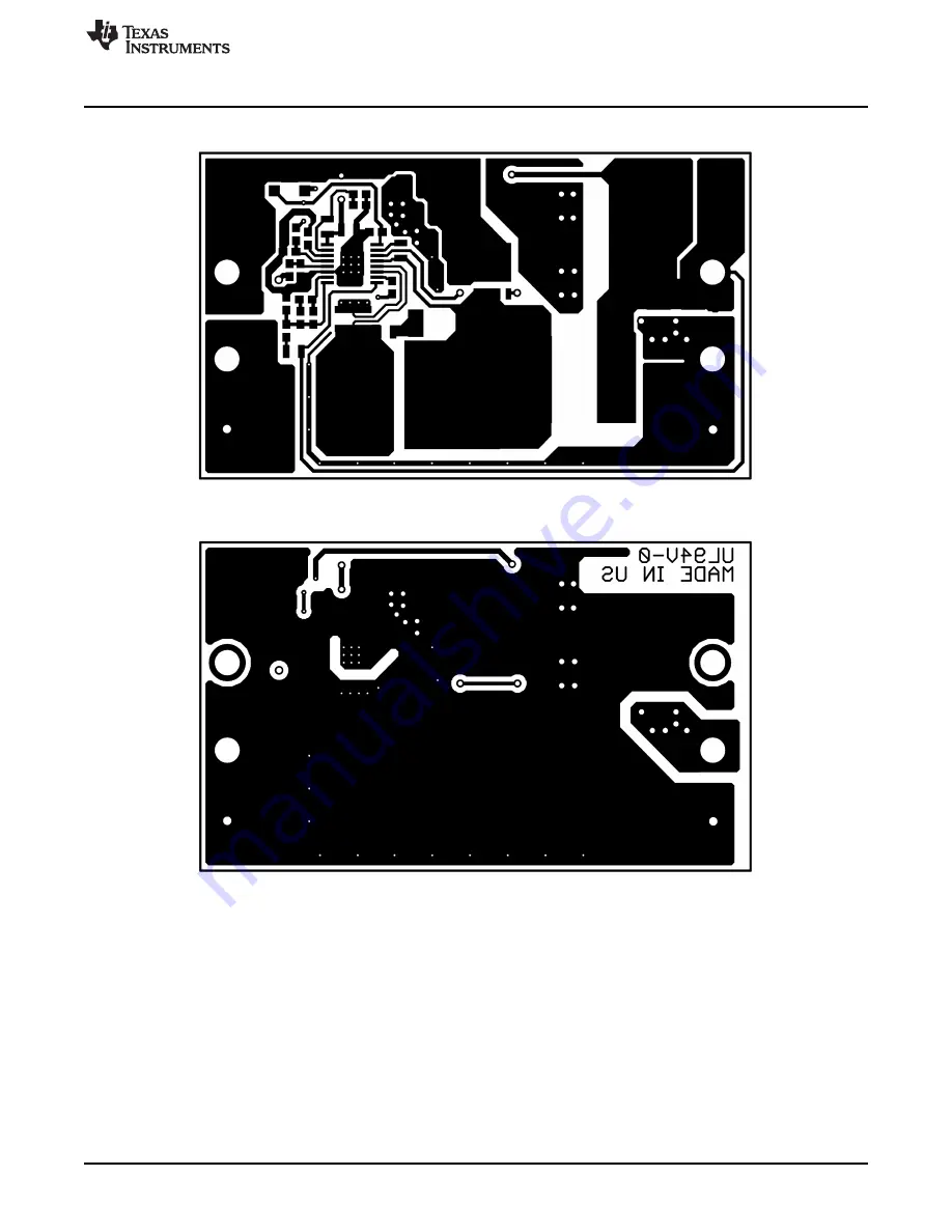
Figure 9. LM25088-1 and LM25088-2 Top Layer

Figure 10. LM25088-1 and LM25088-2 Bottom Layer

7

SNVA383D – November 2008 – Revised April 2013

AN-1931 LM25088 Evaluation Board

Submit Documentation Feedback

Copyright © 2008–2013, Texas Instruments Incorporated

Summary of Contents for LM25088

Page 1: ...or silkscreen The printed circuit board consists of two layers 2 ounce of copper top and bottom and the board size is 2 55x1 5x0 5 inches Specification LM25088 1 LM25088 2 Input Voltage Range 5 5V to 36V 5 5V to 36V Output Voltage 5 0V 5 0V Max Average Load Current 7A 7A Load Regulation 2 2 Current Limit Type Cycle by cycle current limit Hiccup Mode Restart Frequency 250 kHz 5 Oscillator Dithering...

Page 2: ...onably sure that it will affect the efficiency adversely Few parameters can be correct in a switching power supply without creating losses and potentially damaging heat 2 4 Over Current Protection The LM25088 1 and LM25088 2 evaluation boards are both configured with over current protection schemes The LM25088 1 employs a cycle by cycle current limiting while the LM25088 2 is configured for a hicc...

Page 3: ...oards Conditions Input Voltage 24VDC Output Current 4A to 7A Bandwidth Limit 20 MHz Traces Bottom Trace Output Current Amps div 2A Top Trace Output Voltage response Volts div 100 mV Horizontal Resolution 500 µs div Figure 3 Transient Response 3 SNVA383D November 2008 Revised April 2013 AN 1931 LM25088 Evaluation Board Submit Documentation Feedback Copyright 2008 2013 Texas Instruments Incorporated...

Page 4: ...Input Voltage 24VDC Output Current 7A Bandwidth Limit 20 MHz Trace Output Ripple Volts div 50 mV Horizontal Resolution 5 0 µs div Figure 5 Output Voltage Ripple Figure 6 Conducted Emissions Measured at the Input of a LM25088 1 Evaluation Board 4 AN 1931 LM25088 Evaluation Board SNVA383D November 2008 Revised April 2013 Submit Documentation Feedback Copyright 2008 2013 Texas Instruments Incorporate...

Page 5: ...5088 2 Evaluation Boards Figure 7 LM25088 1 W Dithering Schematic Figure 8 LM25088 2 W Restart Schematic 5 SNVA383D November 2008 Revised April 2013 AN 1931 LM25088 Evaluation Board Submit Documentation Feedback Copyright 2008 2013 Texas Instruments Incorporated ...

Page 6: ...rata GRM188R72A104KA35D CAP CER 1 µF 100V X7R 0603 LM25088 1 C14 0 022 µF C0603 Murata GRM188R71C223KA01D CAP CER 22000 pF 16V 10 X7R LM25088 0603 2 D1 Schottky D2PAK On Semi MBRB1545CT Schottky Rectifiers 15A 45V Diode D2 NU SOD123 NU NU NU L1 6 8 µH HC9 series Coiltronics HC9 6R8 R INDUCTOR HIGH CURRENT 6 8 µH Q1 MOSFET SO 8 Vishay IR SI7848DP MOSFET N CH 40V PWR PAK SO8 R1 54 9 kΩ R0805 Rohm MC...

Page 7: ...e 9 LM25088 1 and LM25088 2 Top Layer Figure 10 LM25088 1 and LM25088 2 Bottom Layer 7 SNVA383D November 2008 Revised April 2013 AN 1931 LM25088 Evaluation Board Submit Documentation Feedback Copyright 2008 2013 Texas Instruments Incorporated ...

Page 8: ... Figure 11 LM25088 2 Silk Screen Figure 12 LM25088 1 Silk Screen 8 AN 1931 LM25088 Evaluation Board SNVA383D November 2008 Revised April 2013 Submit Documentation Feedback Copyright 2008 2013 Texas Instruments Incorporated ...

Page 9: ...esponsible for compliance with all legal regulatory and safety related requirements concerning its products and any use of TI components in its applications notwithstanding any applications related information or support that may be provided by TI Buyer represents and agrees that it has all the necessary expertise to create and implement safeguards which anticipate dangerous consequences of failur...

Reviews: