


www.ti.com
EVM Software
5
SNVU546C – October 2017 – Revised May 2018
Submit Documentation Feedback
Copyright © 2017–2018, Texas Instruments Incorporated
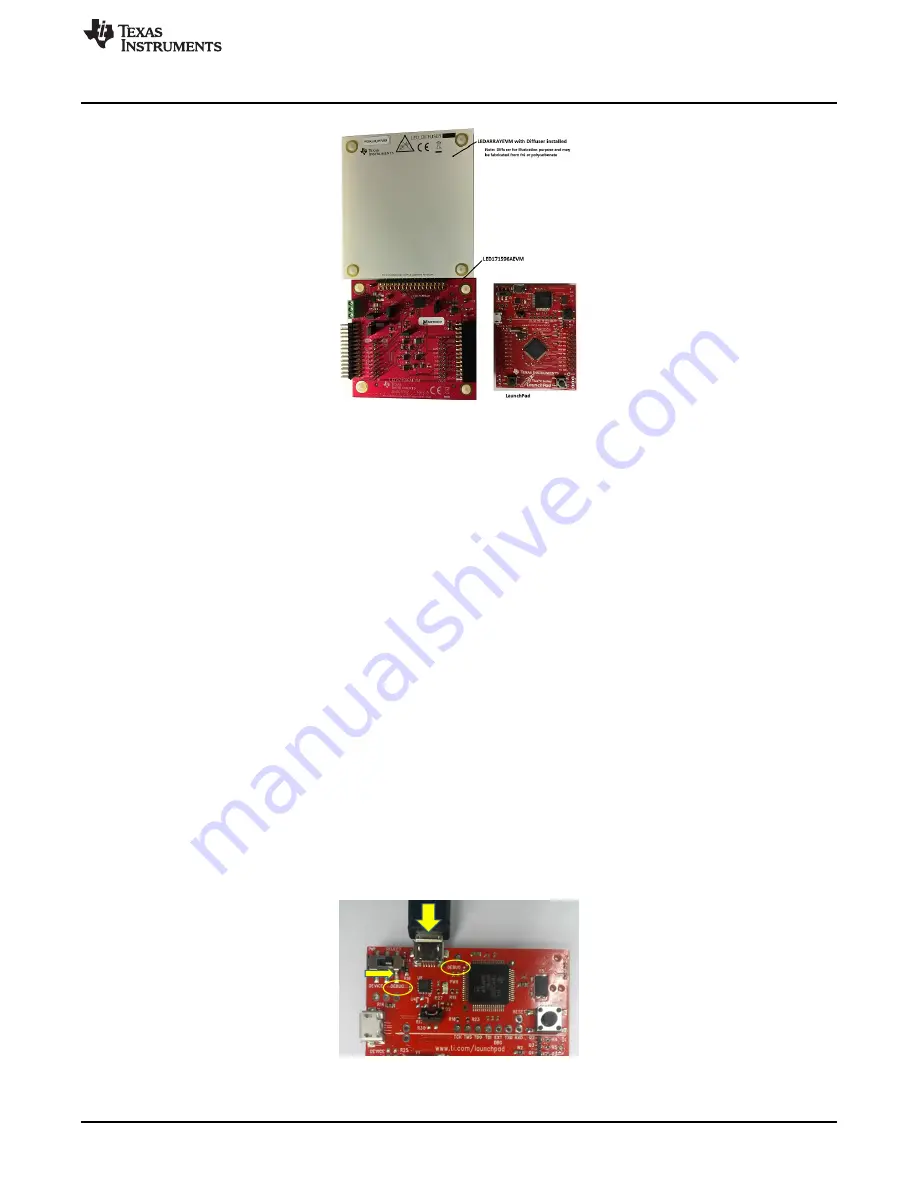
Using the LED171596AEVM Evaluation Module
Figure 3. Tiva LaunchPad (EK-TM4C123GXL) and LED171596A EVM
3.1
Minimum Procedure for Turning on the LEDs
The minimum procedure for turning on the LEDs is as follows:
1. Set the Power Select Switch on Tiva LaunchPad to debug (refer to
Figure 4
).
2. Connect the LaunchPad board to the LED171596AEVM board (refer to
Figure 5
).
3. Verify jumper pin setting (refer to
Figure 2
).
4. Connect micro USB cable to the debug port of LaunchPad board and connect PC (refer to
Figure 4
).
5. Install Tiva ICDI driver.
6. Verify the “Tiva Stellaris
®
Virtual Serial Port” and “Stellaris In-Circuit Debug Interface” on Windows
Device Manager.
7. Connect optional external power and ground to the board.
8. Turn on the external supplies (if used).
9. Install and run EVM software.
10. Make sure the “Hardware Connected” message on the status bar.
11. Click “Control” menu.
12. Click “Enable Pin” button.
13. Click “Enable Backlight” checkbox.
3.2
EVM and Tiva LaunchPad Setup
Connect a micro USB cable to the debug port (power/ICDI) and set the power select switch (PWR
SELECT) to debug (ICDI).
Figure 4. USB Cable Connection and PWR Switch Setting, TM4C123GXL


