


Hardware Configuration
6
SPRUI11B – January 2015 – Revised March 2019
Copyright © 2015–2019, Texas Instruments Incorporated
LAUNCHXL-F28069M Overview
5.2
Serial Connectivity
The LAUNCHXL-F28069M has a USB to UART adapter built in. This makes it easy to print debug
information back to the host PC even in isolated environments. The F28069M device on this LaunchPad
contains two SCI (UART) peripherals, while the LaunchPad has three places these peripherals need to be
routed. Because of this, a serial connectivity mux has been added to the board to make configuration of
the SCI routing easy. Routing is configured via two jumpers (JP6 and JP7). Configure the jumpers as
shown in
for the serial connectivity you desire.
Table 1. Serial Connectivity
MUX_SEL
(JP7)
CH_SEL(JP
6)
Function
ON
ON
USB/UART Disabled; J1.3 and J1.4 – GPIO28 and GPIO29; J7.3 and J7.4 – GPIO15 and GPIO58
ON
OFF
USB/UART – GPIO28 and GPIO29, J1.3 and J1.4 – Hi-Z; J7.3 and J7.4 – GPIO15 and GPIO58
OFF
ON
USB/UART – GPIO15 and GPIO58; FAULT/OCTW – GPIO28 and GPIO29; J7.3 and J7.4 – Hi-Z
OFF
OFF
USB/UART – GPIO15 and GPIO58; FAULT/OCTW – GPIO28 and GPIO29; J7.3 and J7.4 – Hi-Z
NOTE:
If the USB Serial COM Port is not identified by the computer, reprogram the XDS100v2
EEPROM using
5.3
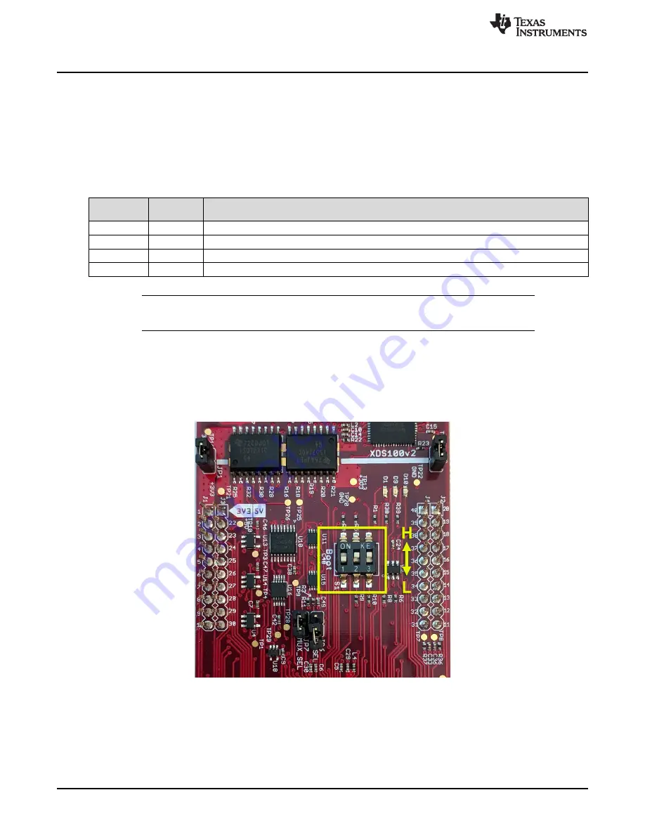
Boot Mode Selection
The LaunchPad's F28069M device includes a boot ROM that performs some basic start-up checks and
allows for the device to boot in many different ways. Most users will either want to perform an emulation
boot or a boot to flash (if they are running the application standalone). S1 has been provided to allow
users to easily configure the pins that the boot ROM checks to make this decision.
Figure 3. Boot Switch Orientation