

7-segment
Display Code
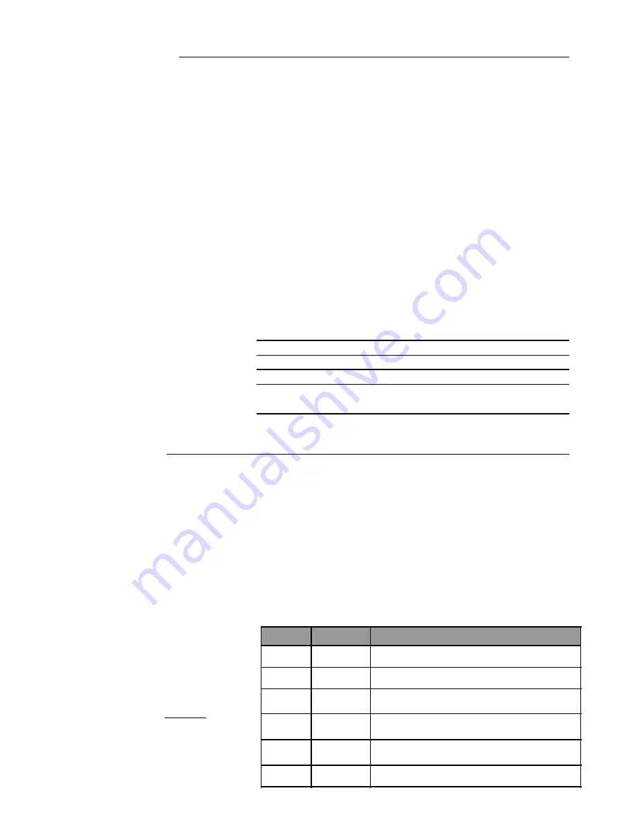
Fault information
Troubleshooting Information
1
Current overload
1) Check MH calibration setting
2,3,7
Current Unbalance
1) Possible high resistance connection caused by an open circuit condition for a
motor phase.
4
Phase reversal
1)
Phase wiring is installed wrong.
2)
Operating frequency for phase current is below 35Hz.
5
Over Temperature
1)
Open or loose connection on sensor wiring.
2)
ÒCÓ terminal mis-wired to one of the sensor channels.
6
Calibration Error
1)
Calibration setting is either <25A or > 225A setting.
2)
Calibration setting was changed after power was applied to supply voltage.
8
Phase Loss
1) Possible high resistance connection caused by an open circuit condition for
a motor phase.
Operation:
1).
While compressor/motor is off, and no current is being sensed, the 7-segment display will slowly f lash the format
HAxxx, where xxx= MH rating. For example, HA125 = Must Hold. Please see step 7 of the installation section for
information on setting the calibration for current overload.
2).
When the compressor/motor is on and current is being sensed, the 7-segment display will flash a rotating Ò0Ó to
indicate the 2ACE has detected motor current greater than 10 Amp and the motor temperature and current being
monitored are within normal operating conditions.
3).
If mis-wired, the phase reversal protection will de-energize the control circuit output within the one second of
operation. (Caution: phase reversal is not provided when motor current is below 10Amp)
4).
When the 2ACE protector recognizes a trip condition, its control relay (M1, M2) will open. Following a trip
condition, power must be maintained on T1, T2. Automatic power off will result in the elimination of the fault codes
indicated on the fault display.
5).
The 2ACE series has low voltage
protection, but it will automatically
reset when rated voltage is present.
6).
All overloads which result from
current measurement or temperature
sensor inputs require a power off
reset.
7).
Refer to the table at the right if a
fault condition is indicated by the
2ACE module that cannot be
confirmed in the compressor/motor.
Installation:
1).
Before you begin installation measure the line & control voltages to ensure they are correct for the equipment to be
operated. See Specifications and Wiring Diagram for reference.
2).
The
control
terminal M1should be connected to the common side of each contactor coil. M2 should be connected to
the actual common of the contactor control supply. Consider all terminals to present a
shock hazard
if the line voltage
is used for the control voltage.
Do not exceed
the 2.5 Amp, 250VAC rating for the control circuit connected to
terminals M1 and M2.
3).
Connect the motor winding thermistor wiring to the corresponding terminals designated as C, S1, S2, S3. Terminal
ÒCÓ is
not common
and is +5 volt rail for thermistor interface.
4).
If applicable, connect the current transducer output to terminals designated as ÒBÓ and ÒGÓ. Terminal ÒGÓ is
electrically at the same potential as T1. The label shows the hidden line connections between these two terminals.
5).
Connect the control voltage wiring to the terminals designated at TI and T2.
Please note
that T1 is the lower
electrical potential with respect to terminal T2.
Keep power off
until the 2ACE is properly calibrated and connected to
all wiring. Control Voltage rating is 24VDC or 24VAC.
6).
Pass phase ÒAÓ through 2ACE orifice designated on top label as ÒAÓ. Repeat for phases ÒBÓ and ÒCÓ. Operating
frequency is limited to 50/60Hz.
7).
Adjust the Must Hold (MH) amperes
by selecting the corresponding DIP
switches such that they add together to
equal the MH ratings for the leads passing
through the module.
Consult
compressor/motor manufacturer
for
MH hold calibration setting. These may
vary with motor wiring selections.
8).
Apply power to supply voltage at T1
and T2. (24VDC or 24VAC)
Units Minimum Typical Maximum
Operating Temperature Range
oC -40
-
+70
Supply Voltage
(Rated 24 VAC at 0.240 A Loa
Vac
18
24
30
Rated Line Frequency
Hz
45
50/60
62
Low Voltage Cut-Out Trip
Vac
15
16
17
Low Voltage Cut-In Reset
Vac
18
Low Voltage Response Time
(Supply 100% to 50%)
Sec
0.150
0.200
0.250


