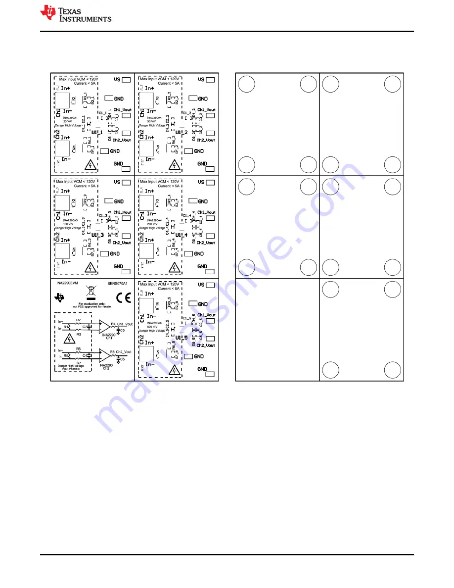
6.2 PCB Layout
Figure 6-6
through
Figure 6-12
show the PCB layout for the INA2290EVM.
Figure 6-6. INA2290EVM Top Overlay
Figure 6-7. INA2290EVM Bottom Overlay
www.ti.com
Schematic, PCB Layout, and Bill of Materials
SBOU243A – SEPTEMBER 2020 – REVISED DECEMBER 2020
Submit Document Feedback
INA2290EVM
11
Copyright © 2020 Texas Instruments Incorporated


