background image

ALP Software Setup

www.ti.com

12

SNLU241A – December 2018 – Revised April 2019

Submit Documentation Feedback

Copyright © 2018–2019, Texas Instruments Incorporated

DS90Ux941AS-Q1EVM User's Guide

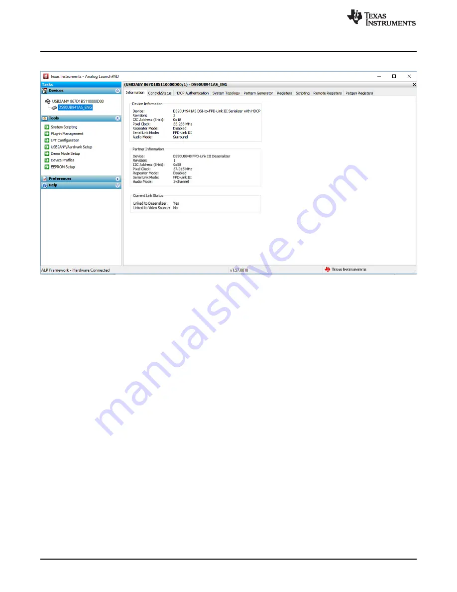
After selecting the DS90Ux941AS-Q1, the screen shown in

Figure 6

should appear.

Figure 6. Follow-Up Screen

Summary of Contents for DS90Ux941AS-Q1EVM

Page 1: ... bit color depth Contents 1 General Description 3 2 Features 3 3 System Requirements 4 4 Contents of the Demo Evaluation Kit 4 5 Applications Diagram 4 6 Typical Configuration 4 7 Quick Start Guide 5 8 Default Jumper Settings 6 9 Default Switch Settings 6 10 Demo Board Connections 6 11 ALP Software Setup 10 12 Troubleshooting ALP Software 19 13 Typical Connection and Test Equipment 23 14 Equipment...

Page 2: ...9 USB2Any Schematic 35 30 Top Overlay 36 31 Top Solder 37 32 Layer1 Top 38 33 Layer 6 Bottom 39 34 Layer6 Solder Bottom 40 35 Layer6 Bottom Overlay 41 36 Drill Drawing 42 37 Board Dimensions 43 List of Tables 1 Default Board Jumper Settings 6 2 Default Board Switch Settings 6 3 Power Supply 6 4 FPD Link III Output Signals P1 6 5 DSI Input Signals 7 6 USB2ANY Connector 7 7 I2C CCI Interface Header ...

Page 3: ...pairs reduces the interconnect size and weight and simplifies system design EMI is minimized by the use of low voltage differential signaling data scrambling and randomization The demo board is not intended for EMI testing The demo board was designed for easy accessibility to device pins with tap points for monitoring or applying signals additional pads for termination and multiple connector optio...

Page 4: ...i com 4 SNLU241A December 2018 Revised April 2019 Submit Documentation Feedback Copyright 2018 2019 Texas Instruments Incorporated DS90Ux941AS Q1EVM User s Guide 3 System Requirements To demonstrate the following is required 1 FPD Link III compatible Deserializer 1 DS90Ux940 Q1 DS90Ux948 Q1 up to 1080p60 2 DSI source 3 Optional I2 C controller 4 Power supply for 12 V at 1 A required 4 Contents of ...

Page 5: ...ault factory setting S6 MODE_SEL1 1 default factory setting S5 PDB and INTB OFF PDB and INTB will be pulled up to VDDIO default factory setting 2 Connect P1 DOUT 1 0 to a compatible Deserializer for example the DS90Ux940 Q1 DS90Ux948 Q1 using STP cable default 3 Connect J28 to 12V a Optional power options available see Table 3 4 Plug in DSI source to J8 5 Connect J14 with miniUSB 5 pin_ to USB A 4...

Page 6: ...2 Default Board Switch Settings SWITCH SWITCH SETTINGS S1 1 3 ON S2 4 ON 1 3 5 8 OFF S3 1 ON 2 8 OFF S5 1 2 OFF S6 1 ON 2 8 OFF 10 Demo Board Connections Table 3 Power Supply DESIGNATOR SIGNAL DESCRIPTION J28 12 V 12 V 5 Main Power Single 12V power connector that supplies power to the entire board J27 1 Optional 1 1 V 1 1 V 5 Alternative to Main Power If used remove R103 J30 1 Optional 1 8 V 1 8 V...

Page 7: ... DSI1_D3_P DSI1_D3_N DSI1 D3 input Table 6 USB2ANY Connector DESIGNATOR DESCRIPTION J14 mini USB 5 pin Table 7 I2C CCI Interface Header DESIGNATOR SIGNAL J11 1 VDDI2C J11 2 SCL J11 3 SDA J1 4 GND Table 8 GPIO Audio Interface DESIGNAT OR SIGNAL DESCRIPTION J12 2 I2S_DC GPIO2 Slave Mode I2S Data Input Remote or Local I O J12 4 I2S_DD GPIO3 Slave Mode I2S Data Input Remote or Local I O J12 8 I2S_DB G...

Page 8: ...1 2 DSI Lanes 10 3 DSI Lanes 11 4 DSI Lanes Non continuous Clock Mode 0 Continuous mode 1 Non continuous mode COAX 0 Enable FPD Link III for twisted pair cabling 1 Enable FPD Link III for coaxial cabling Disable DSI 0 Enable DSI 1 Disable DSI 1 Only set one high Table 11 Configuration Select MODE_SEL0 SW DIP8 S2 1 MODE NO VTARGET VOLTAGE RANGE VTARGET STRAP VOLTAGE SUGGESTED STRAP RESISTORS 1 TOL ...

Page 9: ...V VDD18 0 441 V VDD18 0 472 V VDD18 0 794 51 1 40 2 0 1 1 4 0 526 V VDD18 0 556 V VDD18 0 590 V VDD18 1 001 40 2 51 1 1 0 0 5 0 643 V VDD18 0 673 V VDD18 0 708 V VDD18 1 211 30 1 61 9 1 0 1 6 0 763 V VDD18 0 790 V VDD18 0 825 V VDD18 1 421 18 7 71 5 1 1 0 7 0 880 V VDD18 V VDD18 V VDD18 1 8 10 OPEN 1 1 1 The strapped values can be viewed and or modified in the following register locations SPLIT La...

Page 10: ...Next button 3 Select the location to install the ALP software and then select the Next button 4 Select the location for the start menu shortcut and then select the Next button 5 There will then be a screen that allows the creation of a desktop icon After selecting the desired choices select the Next button 6 Select the Install button and the software will then be installed to the selected location...

Page 11: ...nnected to the PC Execute Analog LaunchPAD shortcut from the start menu The default start menu location is under All Programs Texas Instruments Analog LaunchPAD vx x x Analog LaunchPAD to start MainGUI exe Figure 4 Launching ALP The application should come up in the state shown in the figure below If it does not see Section 12 Troubleshooting ALP Software Under the Devices tab click on DS90Ux941AS...

Page 12: ...cember 2018 Revised April 2019 Submit Documentation Feedback Copyright 2018 2019 Texas Instruments Incorporated DS90Ux941AS Q1EVM User s Guide After selecting the DS90Ux941AS Q1 the screen shown in Figure 6 should appear Figure 6 Follow Up Screen ...

Page 13: ...d April 2019 Submit Documentation Feedback Copyright 2018 2019 Texas Instruments Incorporated DS90Ux941AS Q1EVM User s Guide 11 6 Information Tab The Information tab is shown in Figure 7 Note that the device revision could be different Figure 7 ALP Information Tab ...

Page 14: ...r 2018 Revised April 2019 Submit Documentation Feedback Copyright 2018 2019 Texas Instruments Incorporated DS90Ux941AS Q1EVM User s Guide 11 7 Pattern Generator Tab The SER Pattern Generator tab is shown in Figure 8 Figure 8 ALP Pattern Generator Tab ...

Page 15: ...NLU241A December 2018 Revised April 2019 Submit Documentation Feedback Copyright 2018 2019 Texas Instruments Incorporated DS90Ux941AS Q1EVM User s Guide 11 8 Registers Tab The Register tab is shown in Figure 9 Figure 9 ALP Registers Tab ...

Page 16: ...umentation Feedback Copyright 2018 2019 Texas Instruments Incorporated DS90Ux941AS Q1EVM User s Guide 11 9 Registers Tab Address 0x00 Selected Figure 10 shows the Address 0x00 selected Note that the Value box will now show the hex value of that register Figure 10 ALP Device ID Selected ...

Page 17: ...e expanded Address 0x00 reveals the content for each bits Any register address displayed can be expanded Figure 11 ALP Device ID Expanded Users can change any RW Type register by writing the hex value into the Value box or by clicking the checkboxes next to each register bit A check mark indicates a 1 or R while a blank checkbox indicates a 0 or W Click the Apply button to write to the register an...

Page 18: ...wn in Figure 12 Figure 12 ALP Scripting Tab The script window provides a full Python scripting environment to run scripts and interact with the device in an interactive or automated fashion WARNING Directly interacting with devices either through register modifications or calling device support library functions can effect the performance and or functionality of the user interface and may even cra...

Page 19: ...e 12 1 ALP Loads the Incorrect Profile If ALP opens with the incorrect profile loaded the correct profile can be loaded from the USB2ANY Aardvark Setup found under the tools menu Figure 13 USB2ANY Setup Highlight the incorrect profile in the Defined ALP Devices list and press the remove button Figure 14 Remove Incorrect Profile Find the correct profile under the Select a Daughter Board list highli...

Page 20: ... December 2018 Revised April 2019 Submit Documentation Feedback Copyright 2018 2019 Texas Instruments Incorporated DS90Ux941AS Q1EVM User s Guide Figure 15 Add Correct Profile Select Ok and the correct profile should now be loaded Figure 16 Finish Setup ...

Page 21: ... Figure 17 ALP No Devices Error It may also be that the USB driver is not installed Check the device manager There should be a HID compliant device under the Human Interface Devices as shown in Figure 18 Figure 18 Windows 10 ALP USB Driver The software should start with only DS90Ux941AS Q1 in the Devices drop down menu If there are more devices then the software is most likely in demo mode When th...

Page 22: ...rporated DS90Ux941AS Q1EVM User s Guide Figure 19 ALP in Demo Mode Disable the demo mode by selecting the Preferences drop down menu and un checking Enable Demo Mode Figure 20 ALP Preferences Menu After demo mode is disabled the ALP software will poll the ALP hardware The ALP software will update and have only DS90Ux941AS Q1 under the Devices drop down menu ...

Page 23: ...ed to generate signals for the Serializer inputs 1 Digital Video Source for generation of specific display timing such as Digital Video Processor or Graphics Controller GPU with OpenLDI output 2 Any other signal generator video source This video generator may be used for video signal sources for DVI or DP 3 Any other signal video generator that provides the correct input levels as specified in the...

Page 24: ...erator Astrodesign www astro americas com Logic Analyzer Keysight www keysight com Corelis CAS 1000 I2C E I2C Bus Analyzer and Exerciser Products www corelis com products I2C Analyzer htm Aardvark I2C SPI Host Adapter Part Number TP240141 www totalphase com products aardvark_i2cspi 15 Cable References For optimal performance TI recommends a Shielded Twisted Pair STP 100 Ω differential impedance an...

Page 25: ...1 12 C40 C51 C66 CAP CERM 10 pF 50 V 5 C0G NP0 0402 MuRata GRM1555C1H100JA01D 3 13 C44 CAP CERM 47 uF 16 V 20 X5R 1210 MuRata GRM32ER61C476ME15L 1 14 C45 CAP TA 100 uF 16 V 20 0 1 ohm SMD Kemet T495D107M016ATE100 1 15 C46 CAP CERM 1 uF 16 V 10 X7R 0603 TDK C1608X7R1C105K080AC 1 16 C47 CAP CERM 3300 pF 50 V 10 X7R 0402 MuRata GRM155R71H332KA01D 1 17 C48 C50 CAP CERM 1 uF 16 V 10 X5R 0603 MuRata GRM...

Page 26: ... 120 ohm 100 MHz 3 A 0603 MuRata BLM18SG121TN1D 3 47 LBL 1 Thermal Transfer Printable Labels 1 250 W x 0 250 H 10 000 per roll Brady THT 13 457 10 1 48 P1 HSD Right Angle Plug 4 Leads 2mm Pitch TH Rosenberger D4S20F 40MA5 Z 1 49 Q1 Q2 Q3 MOSFET N CH 50 V 0 22 A SOT 23 Fairchild Semiconductor BSS138 3 50 R1 R2 RES 100 1 0 063 W AEC Q200 Grade 0 0402 Vishay Dale CRCW0402100RFKED 2 51 R3 R7 R8 R10 R6...

Page 27: ...T 3 poles SMT CTS Electrocomponents 219 3LPST 1 78 S2 S3 S6 Switch Slide SPST 8 poles SMT CTS Electrocomponents 219 8MST 3 79 S4 S7 S8 SWITCH TACTILE SPST NO 0 02A 15V TH Panasonic EVQ PAD04M 3 80 S5 Switch 2 SPST 0 15 A 30 V TH Grayhill 78B02ST 1 81 SH J1 SH J2 SH J3 SH J4 SH J5 Shunt 2mm Gold plated Black Samtec 2SN BK G 5 82 U1 99dB SNR Stereo ADC with Single Ended Inputs PW0014A TSSOP 14 Texas...

Page 28: ...SCRIPTION MANUFACTURER PART NUMBER QTY 91 U10 Ultra Low Jitter Programmable Oscillator with Internal EEPROM SIA0008B QFM 8 Texas Instruments LMK61E0M SIAR 1 92 U11 DSI to FPD Link III Bridge Serializer with HDCP RTD0064F VQFNP 64 Texas Instruments DS90UH941ASRTDRQ1 or DS90UB941ASRTDRQ1 1 93 Y1 OSC 12 288 MHz 3 3 Vdc SMD ECS Inc ECS 8FA3X 122 8 TR 1 94 Y2 Crystal 24 000 MHz 20pF SMD ECS Inc ECS 240...

Page 29: ...EXT CONN 3 3V 1 8V 1 1V Power LEDs Audio ADC 5V EXT UC 29 SNLU241A December 2018 Revised April 2019 Submit Documentation Feedback Copyright 2018 2019 Texas Instruments Incorporated EVM PCB Schematics Appendix A SNLU241A December 2018 Revised April 2019 EVM PCB Schematics Figure 23 Top Level Schematic ...

Page 30: ...I1_D1_P DSI1_D1_N DSI1_D1_P DSI1_D2_N DSI1_D2_P DSI1_D2_N DSI1_D2_P DSI1_D3_N DSI1_D3_P DSI1_D3_N DSI1_D3_P VDDL11 VDDP11 VDDP11 VDDHS11 VDDHS11 GND SDA SCL REFCLK VDD33 REFCLK J32 OSC EN D_GPIO0 MOSI D_GPIO1 MISO D_GPIO2 SPLK D_GPIO3 SS SCLK SDIN GPIO0 SWC GPIO1 MCLK 0 R137 GND GND SH J5 4 7k R116 GND 10uF C112 1uF C113 0 1uF C114 GND VDD33 0 R115 SCL_MSP SDA_MSP OE 1 ADD 2 GND 3 SCL 8 OUTP 4 OUT...

Page 31: ...7 0 R63 0 R64 0 R55 10 0k R27 10 0k R38 10 0k R18 10 0k R29 10 0k R56 10 0k R54 10 0k R66 0 R67 10 7k R26 10 7k R39 10 7k R30 10 7k R17 10 7k R53 10 7k R57 64 9k R44 64 9k R21 64 9k R35 64 9k R12 64 9k R48 64 9k R62 40 2k R43 40 2k R22 40 2k R34 40 2k R13 40 2k R49 40 2k R61 16 2k R52 16 2k R58 16 2k R25 16 2k R40 16 2k R16 16 2k R31 41 2k R23 41 2k R42 41 2k R33 41 2k R14 41 2k R60 41 2k R50 30 9...

Page 32: ...1_D1_P DSI1_D1_N DSI1_D0_P DSI1_D0_N DSI SCL SDA SDA SCL PDB DSI0_CLK_N DSI0_CLK_P DSI0_D0_N DSI0_D0_P DSI0_D1_N DSI0_D1_P DSI0_D2_N DSI0_D2_P DSI0_D3_N DSI0_D3_P DSI1_CLK_N DSI1_CLK_P DSI1_D0_N DSI1_D0_P DSI1_D2_N DSI1_D2_P DSI1_D3_N DSI1_D3_P DSI1_D1_N DSI1_D1_P 1 2 3 4 5 6 7 8 9 10 11 12 13 14 15 17 19 21 23 25 27 29 31 16 18 20 22 24 26 28 30 32 J12 J9 1 3 2 4 5 7 6 8 9 11 10 12 13 15 14 16 17...

Page 33: ... 4 NC 6 GND 2 LM2941LD NOPB U7 22 1k R91 121k R92 5V_SW 5V_SW 4 99k R106 IN 1 IN 2 PG 3 BIAS 4 EN 5 GND 6 SS 7 FB 8 OUT 9 OUT 10 EP 11 TPS74701DRCR U8 1GND 3 1EN 4 1IN 5 1IN 6 2GND 9 2EN 10 2IN 11 2IN 12 2OUT 17 2OUT 18 2RESET 22 1OUT 23 1OUT 24 1RESET 28 EP 29 TPS767D318PWP U9A NC 1 NC 2 NC 7 NC 8 NC 13 NC 14 NC 15 NC 16 NC 19 NC 20 NC 21 NC 25 NC 26 NC 27 TPS767D318PWP U9B VDD_EXT SH J3 12V 1A 1...

Page 34: ...0 R1 100 R2 1uF C4 1uF C8 0 01uF C3 0 01uF C9 VCC 4 TRI STATE 1 GND 2 OUTPUT 3 Y1 1 2 3 J3 L1 L2 10 0k R9 1 6 S1A 3 4 S1C 2 5 S1B FMT MD1 MD0 FMT MD0 MD1 10V 10µF C1 10V 10µF C5 10V 10µF C6 10V 10µF C13 16V 0 1uF C2 16V 0 1uF C7 16V 0 1uF C12 10V 10µF C11 16V 0 1uF C14 10V 10µF C10 Appendix A www ti com 34 SNLU241A December 2018 Revised April 2019 Submit Documentation Feedback Copyright 2018 2019 ...

Page 35: ...2 P2 4 TA2 1 33 P2 5 TA2 2 34 P2 6 RTCCLK DMAE0 35 P2 7 UCB0STE UCA0CLK 36 P3 0 UCB0SIMO UCB0SDA 37 P3 1 UCB0SOMI UCB0SCL 38 P3 2 UCB0CLK UCA0STE 39 P3 3 UCA0TXD UCA0SIMO 40 P3 4 UCA0RXD UCA0SOMI 41 P3 5 TB0 5 42 P3 6 TB0 6 43 P3 7 TB0OUTH SVMOUT 44 P4 0 PM_UCB1STE PM_UCA1CLK 45 P4 1 PM_UCB1SIMO PM_UCB1SDA 46 P4 2 PM_UCB1SOMI PM_UCB1SCL 47 P4 3 PM_UCB1CLK PM_UCA1STE 48 DVSS2 49 DVCC2 50 P4 4 PM_UC...

Page 36: ...December 2018 Revised April 2019 Submit Documentation Feedback Copyright 2018 2019 Texas Instruments Incorporated Board Layout Appendix B SNLU241A December 2018 Revised April 2019 Board Layout Figure 30 Top Overlay ...

Page 37: ...www ti com Appendix B 37 SNLU241A December 2018 Revised April 2019 Submit Documentation Feedback Copyright 2018 2019 Texas Instruments Incorporated Board Layout Figure 31 Top Solder ...

Page 38: ...Appendix B www ti com 38 SNLU241A December 2018 Revised April 2019 Submit Documentation Feedback Copyright 2018 2019 Texas Instruments Incorporated Board Layout Figure 32 Layer1 Top ...

Page 39: ...www ti com Appendix B 39 SNLU241A December 2018 Revised April 2019 Submit Documentation Feedback Copyright 2018 2019 Texas Instruments Incorporated Board Layout Figure 33 Layer 6 Bottom ...

Page 40: ...Appendix B www ti com 40 SNLU241A December 2018 Revised April 2019 Submit Documentation Feedback Copyright 2018 2019 Texas Instruments Incorporated Board Layout Figure 34 Layer6 Solder Bottom ...

Page 41: ...www ti com Appendix B 41 SNLU241A December 2018 Revised April 2019 Submit Documentation Feedback Copyright 2018 2019 Texas Instruments Incorporated Board Layout Figure 35 Layer6 Bottom Overlay ...

Page 42: ...Appendix B www ti com 42 SNLU241A December 2018 Revised April 2019 Submit Documentation Feedback Copyright 2018 2019 Texas Instruments Incorporated Board Layout Figure 36 Drill Drawing ...

Page 43: ...www ti com Appendix B 43 SNLU241A December 2018 Revised April 2019 Submit Documentation Feedback Copyright 2018 2019 Texas Instruments Incorporated Board Layout Figure 37 Board Dimensions ...

Page 44: ...truments Incorporated Revision History Revision History NOTE Page numbers for previous revisions may differ from page numbers in the current version Changes from Original December 2018 to A Revision Page Changed Typical Connection and Test Equipment Images 23 Changed Bill of Materials 25 Changed schematics layouts and board shots 29 ...

Page 45: ...other than TI b the nonconformity resulted from User s design specifications or instructions for such EVMs or improper system design or c User has not paid on time Testing and other quality control techniques are used to the extent TI deems necessary TI does not test all parameters of each EVM User s claims against TI under this Section 2 are void if User fails to notify TI of any apparent defects...

Page 46: ... These limits are designed to provide reasonable protection against harmful interference in a residential installation This equipment generates uses and can radiate radio frequency energy and if not installed and used in accordance with the instructions may cause harmful interference to radio communications However there is no guarantee that interference will not occur in a particular installation...

Page 47: ...y for convenience and should be verified by User 1 Use EVMs in a shielded room or any other test facility as defined in the notification 173 issued by Ministry of Internal Affairs and Communications on March 28 2006 based on Sub section 1 1 of Article 6 of the Ministry s Rule for Enforcement of Radio Law of Japan 2 Use EVMs only after User obtains the license of Test Radio Station as provided in R...

Page 48: ... any interfaces electronic and or mechanical between the EVM and any human body are designed with suitable isolation and means to safely limit accessible leakage currents to minimize the risk of electrical shock hazard User assumes all responsibility and liability for any improper or unsafe handling or use of the EVM by User or its employees affiliates contractors or designees 4 4 User assumes all...

Page 49: ...OR DAMAGES ARE CLAIMED THE EXISTENCE OF MORE THAN ONE CLAIM SHALL NOT ENLARGE OR EXTEND THIS LIMIT 9 Return Policy Except as otherwise provided TI does not offer any refunds returns or exchanges Furthermore no return of EVM s will be accepted if the package has been opened and no return of the EVM s will be accepted if they are damaged or otherwise not in a resalable condition If User feels it has...

Page 50: ...se resources are subject to change without notice TI grants you permission to use these resources only for development of an application that uses the TI products described in the resource Other reproduction and display of these resources is prohibited No license is granted to any other TI intellectual property right or to any third party intellectual property right TI disclaims responsibility for...

Reviews: