www.ti.com
GUI Application
9
SLVUB68 – October 2017
Submit Documentation Feedback
Copyright © 2017, Texas Instruments Incorporated
DRV8873x-Q1EVM User’s Guide
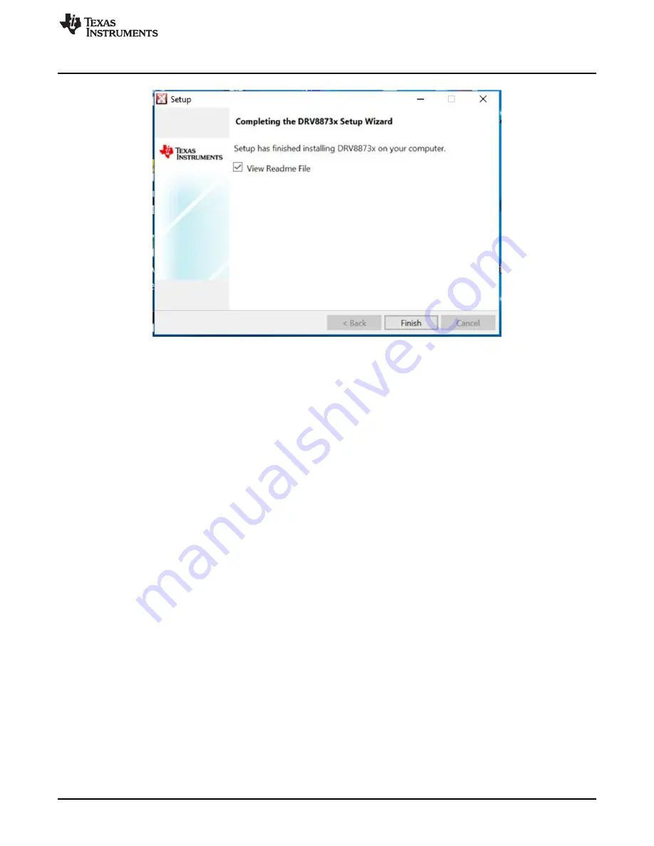
Figure 11. Installation Complete
Page 1: ...ction 2 1 1 Overview 2 1 2 Purpose and Scope 2 2 Hardware and Software Overview 3 2 1 Hardware Connections Overview 3 2 2 Connection Details 3 2 3 LED Lights and Switch Functions 4 3 GUI Application 4...
Page 2: ...e current through the high side FETs and does not require a high power resistor for sensing the current A low power sleep mode is provided to achieve very low quiescent current draw by shutting down m...
Page 3: ...d fans may be required to adequately cool customer provided loads depending on loading conditions 2 1 Hardware Connections Overview The major blocks of the DRV8873x Q1EVM include the DRV8873 Q1 driver...
Page 4: ...n abnormal condition such as overcurrent overtemperature or open load The S1 switch is configured to reset the MSP430G2553 MCU By moving the J2 jumper to the alternate position the switch can be used...
Page 5: ...ion Feedback Copyright 2017 Texas Instruments Incorporated DRV8873x Q1EVM User s Guide Figure 3 User Account Control Step 3 Click the Next button in the Setup DRV8873x window see Figure 4 Figure 4 Set...
Page 6: ...s Guide Figure 5 License Agreement Step 5 Click the I accept the agreement radio button if accepted and then click the Next button see Figure 6 Figure 6 Accepted License Agreement Step 6 Select the i...
Page 7: ...s Incorporated DRV8873x Q1EVM User s Guide Figure 7 Installation Directory Step 7 Click the Next button in the Ready to Install window to begin the installation see Figure 8 Figure 8 Ready to Install...
Page 8: ...corporated DRV8873x Q1EVM User s Guide Figure 9 Desktop Icons When the installation begins the Installing window shows the installation progress see Figure 10 Figure 10 Installation Progress The insta...
Page 9: ...www ti com GUI Application 9 SLVUB68 October 2017 Submit Documentation Feedback Copyright 2017 Texas Instruments Incorporated DRV8873x Q1EVM User s Guide Figure 11 Installation Complete...
Page 10: ...Q1EVM is a micro USB cable and a power supply from 4 5 to 38 V Follow these steps to start up the DRV88873x Q1EVM Step 1 Connect the positive output of the DC power supply to the VM screw terminal and...
Page 11: ...set forth above or credit User s account for such EVM TI s liability under this warranty shall be limited to EVMs that are returned during the warranty period to the address designated by TI and that...
Page 12: ...the antenna types listed in the user guide with the maximum permissible gain and required antenna impedance for each antenna type indicated Antenna types not included in this list having a gain great...
Page 13: ...t the EVM user guide prior to connecting any load to the EVM output If there is uncertainty as to the load specification please contact a TI field representative During normal operation even with the...
Page 14: ...OST OF REMOVAL OR REINSTALLATION ANCILLARY COSTS TO THE PROCUREMENT OF SUBSTITUTE GOODS OR SERVICES RETESTING OUTSIDE COMPUTER TIME LABOR COSTS LOSS OF GOODWILL LOSS OF PROFITS LOSS OF SAVINGS LOSS OF...
Page 15: ...TI Resource NO OTHER LICENSE EXPRESS OR IMPLIED BY ESTOPPEL OR OTHERWISE TO ANY OTHER TI INTELLECTUAL PROPERTY RIGHT AND NO LICENSE TO ANY TECHNOLOGY OR INTELLECTUAL PROPERTY RIGHT OF TI OR ANY THIRD...