


Hardware and Software Overview
3
SLVUB68A – October 2017 – Revised August 2018
Copyright © 2017–2018, Texas Instruments Incorporated
DRV8873xEVM User’s Guide
2
Hardware and Software Overview
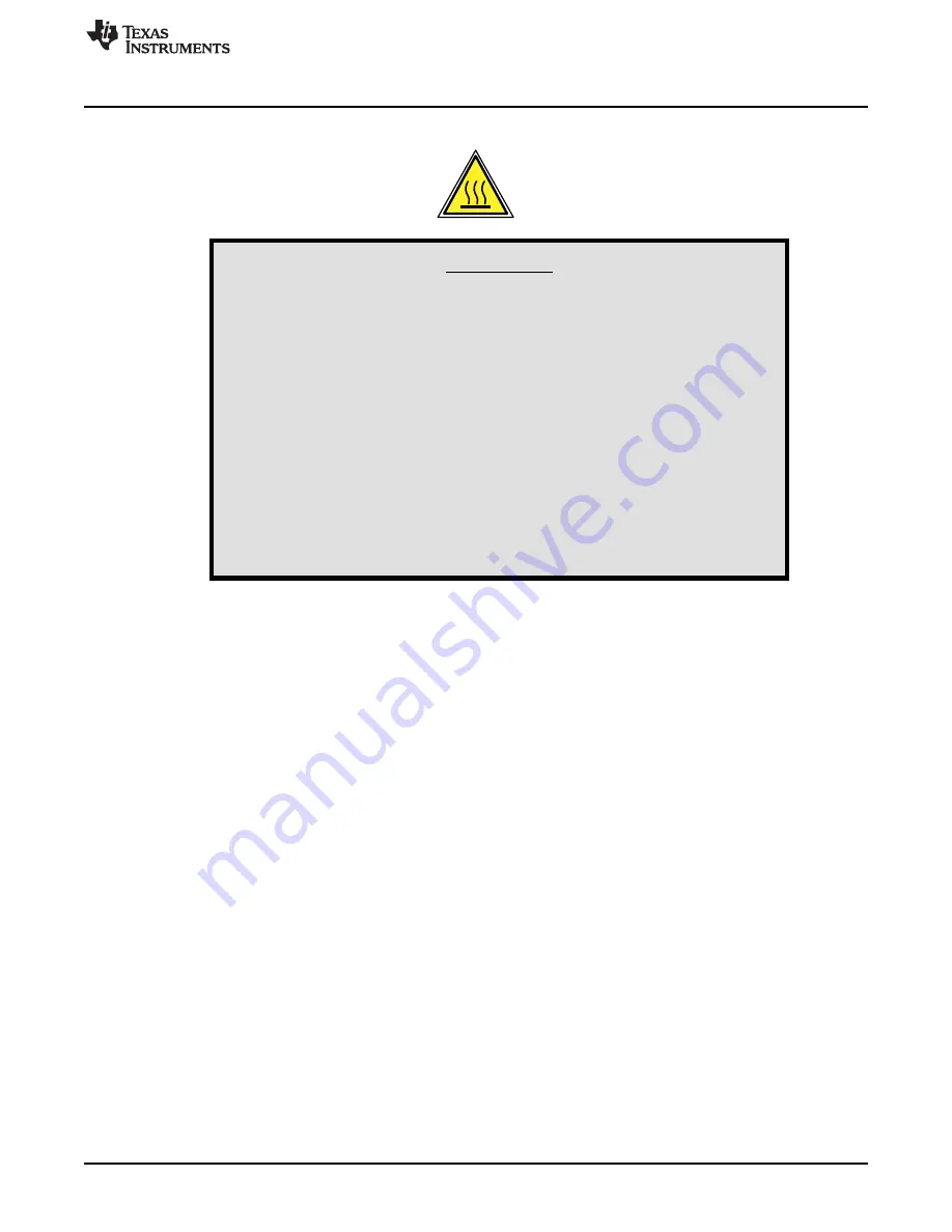
WARNING
Hot surfaces on the DRV8873xEVM include the DRV8873 device (
U1 ) and the area surrounding it.
When operating the DRV8873xEVM between 4-A and 6-A, the
device
overtemperature
warning
should
be
monitored
for
overtemperature warnings. The nFAULT pin indicates when the
device temperature has increased above 140°C and is approaching
thermal shutdown. As with any elevated temperatures, normal
precautions must be followed to avoid direct contact with the hot
surface of the DRV8873xEVM when used in the 4-A to 6-A load
range.
To minimize potential fire hazard, personal injury, or both,
externally provided fans may be required to adequately cool
customer-provided loads depending on loading conditions.
2.1
Hardware Connections Overview
The major blocks of the DRV8873xEVM include the DRV8873 driver, the MSP430G2553 microcontroller
(MCU), the LM9036QMX-3.3/NOPB 3.3-V LDO regulator, and the USB communication. The
DRV8873xEVM is designed for an input supply from 4.5 to 38 V and up to 10-A peak drive current.
The DRV8873 device driver is used to provide the current to the motor or other load. The MCU
communicates with the GUI to control the DRV8873 device.
2.2
Connection Details
shows the power connector and motor phase connector. A supply voltage ranging from 4.5 V to
38 V from a battery or a DC voltage source is connected to the voltage supply pins. The OUT1 and OUT2
pins can be connected to a single motor winding, inductor, or latched relay coil when used in PWM or
PH/EN mode. When used in independent half-bridge mode, the OUT1 pin can drive one load and the
OUT2 pin can drive a second load.