


Acceleration Delay (ms/1% duty cycle)
– 50
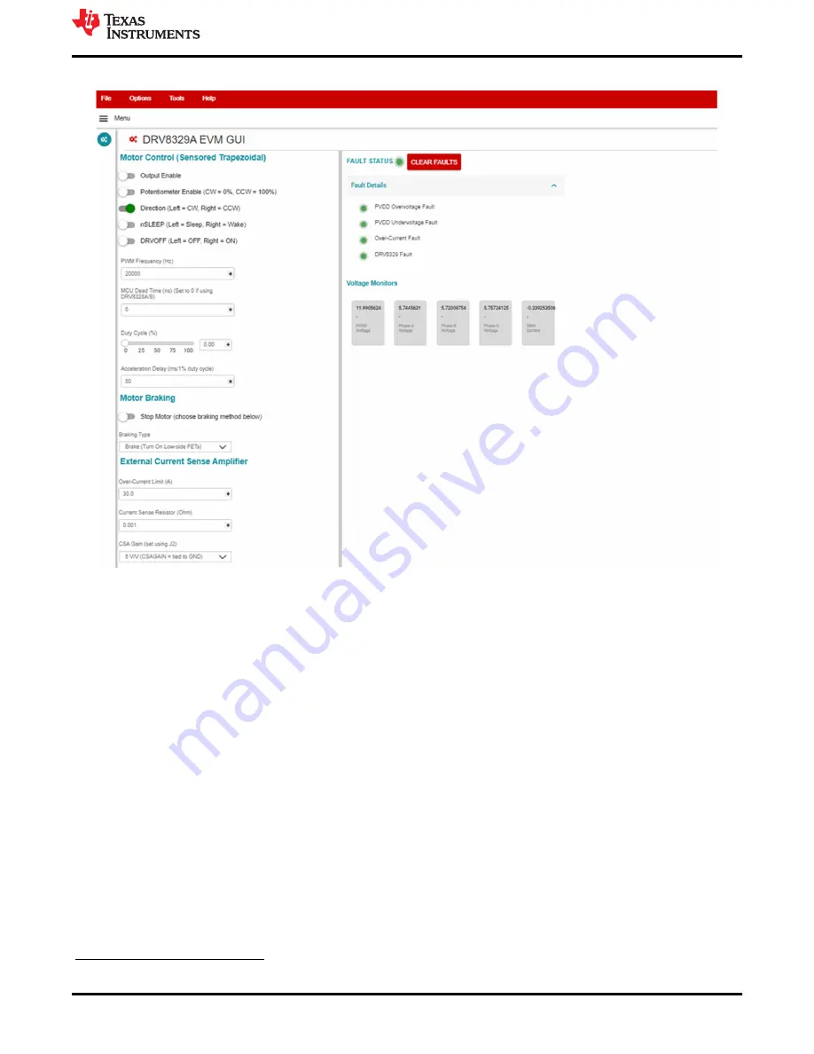
Figure 6-3. DRV8329A_EVM_GUI defaults when connected
6.2 DRV8329x EVM GUI Quick Start Guide
1. Click on the “Output Enable” switch.
2. Enter the PWM frequency in Hz using the “PWM Frequency (Hz)” text box. Press Enter.
3. Adjust the MCU dead time and Acceleration Delay values. You may also use the DT potentiometer to
insert dead time from the DRV8329 rather than the MCU by setting the dead time potentiometer resistance,
enabling the DT_POT jumper, and setting the MCU dead time to 0 ns.
4. To control the motor speed using the speed potentiometer, turn the potentiometer all the way
counterclockwise to set to 0% speed. Click on the “Potentiometer Enable” switch. To not use the
potentiometer to control the motor speed, skip this step.
5. Adjust the “Duty Cycle” slider or enter the duty cycle in the number box to control the speed of the motor
from 0% to 100%.
6. Use the “Direction” switch to switch the direction of the motor.
7. Use the drop-down menu in “Motor Braking” to determine the motor braking type. Click on “Stop Motor” to
stop the method with the selected braking type.
8. If R58 is populated and R11 is not populated, use the nSLEEP switch to put the driver into a low-power sleep
mode.
9. If R69 is populated, use the DRVOFF switch to shut off the gate drivers and Hi-Z the gate driver outputs.
6.3 Using the DRV8329AEVM-GUI
The GUI offers the following features:
MOTOR CONTROL SETTINGS
Firmware and GUI Application
DRV8329AEVM User’s Guide
17
Copyright © 2022 Texas Instruments Incorporated