


u
1 Mechanical _ rev
60 s
200 Hz X
3000 RPM
1 PU
8 poles
1 min
Electrical _ rev
2
Quick Start GUI
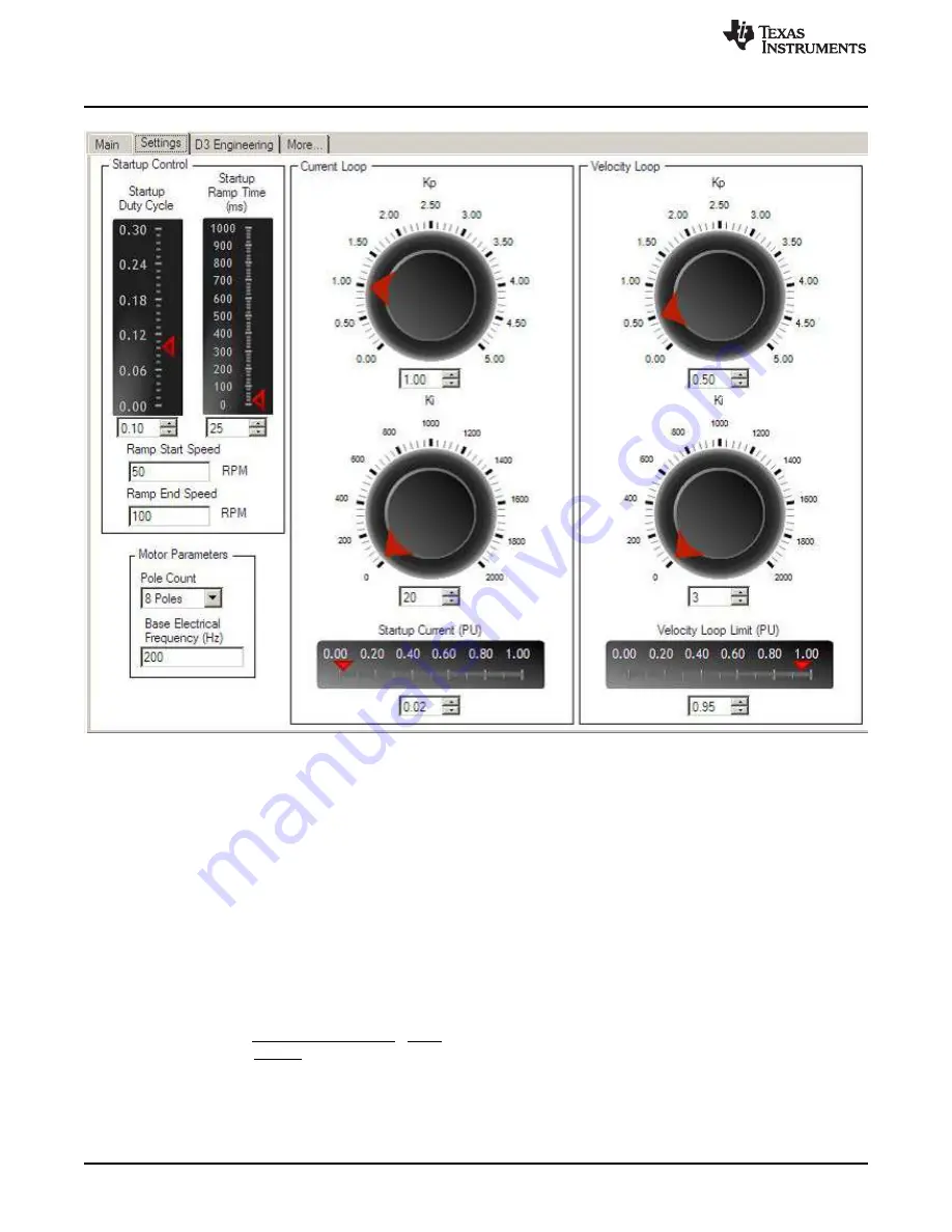
Figure 7. Settings Tab
•
Start-up control: These parameters control how the motor initially ramps up under forced commutation.
The motor must spin and generate some BEMF in order for the sensor-less algorithm to latch on and
take over commutation.
–
Start-up duty cycle: Sets the constant PWM duty cycle given to the motor during the forced
commutation ramp-up phase
–
Start-up ramp time: Sets the time taken to complete the forced commutation ramp-up phase
–
Ramp start speed: Sets the initial speed for the forced commutation ramp-up phase
–
Ramp end speed: Sets the final speed for the forced commutation ramp-up phase
•
Motor parameters
–
Pole count: Choose the number of poles for the motor under test.
–
Base electrical frequency: Sets the scaling of per-unit (PU) speed to motor electrical speed. Use
this equation for the settings shown prior:
•
Current loop: These parameters are associated with the current control loop and are only active when
control mode is set to current or cascade. Current and cascade are the only modes which make use of
the current loop.
8
DRV8303EVM User Guide
SLVU983A – September 2013 – Revised October 2013
Copyright © 2013, Texas Instruments Incorporated