Texas Instruments DRV814x-Q1EVM User Manual Download Page 19

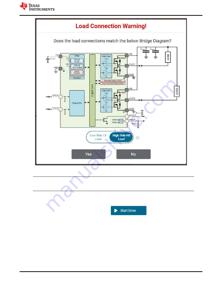
Figure 5-7. DRV824x Independent Half-Bridge Mode High Side and Low Side Load Connection

Note

DRV824x-Q1EVMs with HVSSOP package driver device has OUT1 and OUT2 silk screen labels 
interchanged. This misprint will be fixed in the next revision of these EVMS.

BRIDGE CONTROL

 The Start Drive button allows the software state machine to start running on the MCU. 

Prior to starting, the user may wish to tweak the desired direction, ramp rate, slew rate, as well as check for 

properly connected load connections. After pressing 

, the duty cycle slider(s) become 

available for modification. The output will automatically soft-start using the Ramp Rate parameter.

PASSIVE/ACTIVE DIAGNOSTICS

 The SPI variant features both passive and active diagnostics. The passive 

diagnostics also known as Off-line Passive (OLP), may only be used when 

ENABLE DRIVER

 is disabled 

(Off-state). It will show up in a separate pop-up window as can be seen in 

Figure 5-8

. A representative table 

from the device datasheet is displayed in this window for guidance to perform the passive diagnostics. Each 
row of the table covers a specific combination of user input selection, the corresponding OLP setup and load 
status inference from the OLP_CMP comparator output on the nFAULT pin. See device datasheet for more 
details. The required S_DIAG selection can be made using the GUI for SPI devices. The required DIAG 
jumper setting must be done when 

WAKE

 is Asleep for HW devices prior to enabling passive diagnostics. 

The nSLEEP and DRVOFF inputs are logic 1 while observing passive diagnostics. Inputs for EN/IN1 and 
PH/IN2 are selected using the switches in the GUI. It may take a few seconds for the pull up, pull down 

www.ti.com

EVM GUI Operation

SLVUC46A – MARCH 2021 – REVISED JULY 2021

Submit Document Feedback

DRV824x_DRV814x-Q1EVM User’s Guide

19

Copyright © 2021 Texas Instruments Incorporated

Summary of Contents for DRV814x-Q1EVM

Page 1: ...Setup 14 5 2 Launching the DRV824x_DRV814x Q1EVM GUI Application 14 5 3 Using the DRV824x_DRV814x Q1EVM GUI Application 16 Trademarks All trademarks are the property of their respective owners 1 Revis...

Page 2: ...eep mode is provided to achieve ultra low quiescent current draw by shutting down most of the internal circuitry The device offers voltage monitoring and load diagnostics as well as protection feature...

Page 3: ...VM and DRV814x Q1EVM in the VQFN HotRod package The 28 pin leaded package HVSSOP or HTSSOP version of EVM leverages much of the same design and is also covered by this document From a firmware and GUI...

Page 4: ...mware updates Main supply input A supply voltage ranging from 4 5 VDC to 36 VDC from a battery or a DC voltage source is connected to the large screw thermal block fused and reverse polarity protectio...

Page 5: ...re 3 2 Typically resetting the MCU is not necessary however the MCU will automatically clear the nFAULT indicator on initial power up if you find the fault indicator is set due to cycling the power on...

Page 6: ...out a computer or USB connection You can connect a brushed DC motor across OUT1 and OUT2 terminals of the DRV824x EVM or OUT and GND of the DRV814x EVM or simply an oscilloscope Note No diagnostics ar...

Page 7: ...gure 3 4 illustrates the portions of the EVM associated with the main supply input powering the DRV824x Q1 or DRV814x Q1 device and the associated load s Starting from the upper left and working clock...

Page 8: ...ting period Additionally BOM cost and PCB area is reduced by eliminating a large external power shunt resistor The off time PWM current regulation level can be configured during motor operation throug...

Page 9: ...ediately adjacent to the silk screen label Note PH IN2 signal is not present on DRV814x Q1EVM variants Refer to your EVM schematic for more details Figure 3 6 DRV824x Q1EVM Signal and Control Header 3...

Page 10: ...ly off It is also normal to briefly see this LED flash when the MCU becomes active or RESET is pressed This LED may flash continuously until VM power supply is turned on D3 VM VM supply indicator Norm...

Page 11: ...et for more information regarding pin LVL settings and associated configuration Note IPROPI is common to both hardware and SPI EVM device variants and performs the same function Figure 3 8 DRV824x and...

Page 12: ...r package corresponding to your operating system extract the archive and run the installer In Windows two new ports should be enumerated when the EVM is connected Figure 4 1 Figure 4 1 MSP430 EZFET_LI...

Page 13: ...814x Q1EVM GUI 2 From the gallery click the icon in the latest version and select the installer for your operating system Windows Linux or Mac Refer back to Figure 4 3 in the previous section for a vi...

Page 14: ...situations such as while disconnecting and reconnecting VM power before the power supply capacitors are fully discharged a proper firmware reset may not happen A proper reset is indicated by the STAT...

Page 15: ...in Figure 5 2 Note If the EVM GUI does not register a successful connection after multiple attempts do a firmware update and then select an EVM variant for connecting using the GUI application Figure...

Page 16: ...Variant The Register Map page shown below in Figure 5 4 allows the user to read write values to individual fields Register read back is read Every 1 sec by default Enabling this will start periodicall...

Page 17: ...iagnostics MODE Programs the S_MODE register and will alter the appearance of the BRIDGE CONTROL depending on your selection There is a difference in MODE options between the DRV824x and DRV814x devic...

Page 18: ...er This is especially important when in Independent Half Bridge mode The load connection warning will appear every time the user selects a new mode or repeatedly selects the current mode Figure 5 7 sh...

Page 19: ...DRIVER is disabled Off state It will show up in a separate pop up window as can be seen in Figure 5 8 A representative table from the device datasheet is displayed in this window for guidance to perf...

Page 20: ...of the load current during the sampling window The IPROPI analog output pin available on the header J4 of the EVM can be used for accurate real time measurement using a multimeter or for capturing th...

Page 21: ...mage When operating the EVM at the maximum device specifications and higher ambient temperature external cooling fans may be required to minimize potential fire hazard personal injury or both 5 3 4 Up...

Page 22: ...are subject to change without notice TI grants you permission to use these resources only for development of an application that uses the TI products described in the resource Other reproduction and...

Reviews: