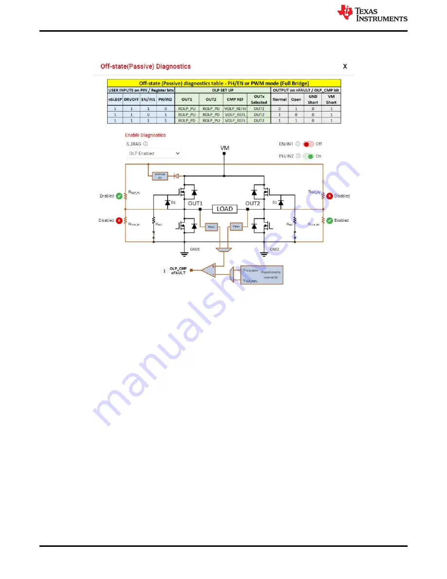
resistors, and the OLP_CMP output status to update due to the latency between the EVM hardware and the
GUI application.
Figure 5-8. Passive Diagnostics Pop-Up Window
The Active Open Load Diagnostics are only for High-Side loads with the DRV824x device, Independent
Half-Bridge mode, and the DRV814x Half-Bridge device. The Active Diagnostics not exist in the Hardware
variants.
•
FAULTS
Press the clear button to clear all the latched faults. Next to the clear button is the
CONFIG
button
for SPI variants. This button allows the user to have more control over the modification of fault reporting. For
example, selecting
Automatic Retry
would allow the faults to clear without any manual interference.
•
BRIDGE CURRENT
The Bridge Current displays moving average and cycle peak load current values
calculated from a window of samples of the voltage V
IPROPI
(V
IPROPI
= R
IPROPI
× IPROPI) on the IPROPI
output. Each periodic window of samples is referred to as a cycle. The samples are captured using the
integrated 10-bit analog to digital converter in the MCU of the EVM. The displayed values are only indicative
of the load current during the sampling window. The IPROPI analog output pin available on the header J4
of the EVM can be used for accurate real-time measurement using a multimeter or for capturing the load
current waveform using an oscilloscope. Current scaling is done by selecting a desired R
IPROPI
resistor with
the IPROPI jumper setting on the current limit headeer J2 of EVM. See
. Match the R
IPROPI
setting on the GUI with the IPROPI jumper setting of the EVM.
Every control also has a help tip associated with it to quickly help the user while running the GUI.
5.3.3 Driver Control Page (HW Device Variant)
There are a few other minor differences between the SPI and HW device variant which are noted below:
•
WAKE
For the Hardware variant, it is necessary for the jumpers to be selected while the device is asleep,
and the default for the HW variant is "asleep". If the user makes changes to the jumpers while the device is
awake, the device will not recognize those changes.
•
ENABLE DRIVER
Directly controls the DRVOFF pin. When the bridge control is active the user cannot
observe the passive diagnostics.
EVM GUI Operation
20
DRV824x_DRV814x-Q1EVM User’s Guide
SLVUC46A – MARCH 2021 – REVISED JULY 2021
Copyright © 2021 Texas Instruments Incorporated


