


R
=
EXT
K
I
LIM
V
REF
)
(
R
INT
V
= V
BOOST
FB
1 +
R
2
R
1
)
(
Hardware Configuration
(3)
where V
FB
= 1.32 V.
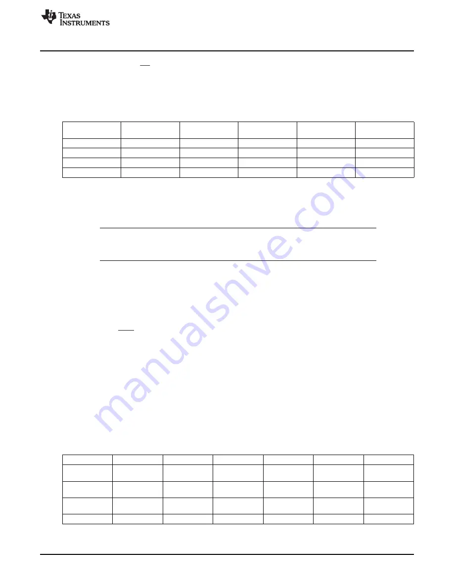
shows the typical values for R1 and R2 and the corresponding output voltages.
Table 9. Boost Voltage and Gain Settings (R1 and R2 Only)
R1
R2
GAIN1
GAIN0
VBST
Vout (Peak to
Peak)
402 k
Ω
18.2 k
Ω
0
0
30
50
392 k
Ω
9.76 k
Ω
0
1
55
100
768 k
Ω
13 k
Ω
1
0
80
150
768 k
Ω
9.76 k
Ω
1
1
105
200
The maximum boost output voltage is 105 V. Program VBST to a value 5 V greater than the largest peak
voltage expected in the system to allow adequate amplifier headroom. Because the programming range
for the boost voltage extends to 105 V, the current through the resistor divider can become significant. The
sum of the feedback resistors R1 and R2 should be greater than 500 k
Ω
.
NOTE:
When the feedback resistor values are greater than 1 M
Ω
, PCB contamination may cause
boost voltage inaccuracies. Keep the board clean from excess solder and flux when
modifying.
3.6.3
Boost Current Limit
The peak inductor current is set by resistor R5 (R
EXT
). The current limit is not a safety mechanism, but the
highest value current the inductor sees each cycle. The inductor must be capable of handling this
programmed limit during normal operation. This can be used to limit the peak current drawn by the boost
converter. The relationship of R
EXT
to I
LIM
is approximated using:
(4)
where I
LIM
is the current limit set by R
EXT
, K = 10500, V
REF
= 1.35 V and R
INT
= 60
Ω
.
3.6.4
Boost Inductor Selection
Inductor selection plays a critical role in the performance of the DRV2667. The range of recommended
inductor values is 3.3
μ
H to 22
μ
H. When a larger inductance is chosen, the DRV2667 boost converter
automatically runs at a lower switching frequency and incurs less switching losses. The larger inductors;
however, may also have a higher equivalent series resistance (ESR), which increases the parasitic
inductor losses. Smaller inductances generally have higher saturation currents; therefore, they are better
suited for maximizing the output current of the boost converter.
lists several sample inductors
that provide adequate performance.
Table 10. Boost Converter Inductor Selection
Manufacturer
Part Number
DCR (
Ω
)
Inductance (µH) ISAT (A)
R
EXT
(
Ω
)
I
LIM
(A)
Coilcraft
LPS4018-
0.08
3.3
1.9
7.32 k
1.9
332MLB
Coilcraft
LPS4018-
0.125
4.7
1.8
7.5 k
1.8
472MLB
TDK
VLS3012T-
0.100
3.3
1.5
9.31 k
1.5
3R3M1R3
TDK
VLS3010
0.130
3.3
1.3
11 k
1.28
21
SLOU323 – June 2013
DRV2667 Evaluation Module
Copyright © 2013, Texas Instruments Incorporated