Texas Instruments DRV2605EVM-CT User Manual Download Page 23

www.ti.com

MSP430 Firmware

6.1

MSP430 Pinout

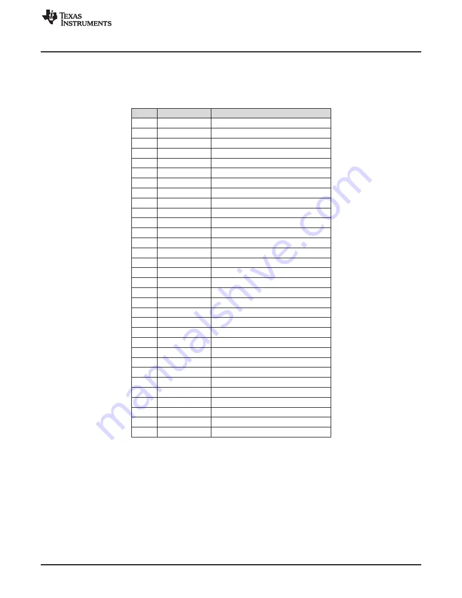
The DRV2605EVM-CT contains a MSP430G2553 low-cost microcontroller, which controls the board and
contains sample haptic effects. The pinout for the microcontroller can be found in

Table 6

.

Table 6. MSP430 Pinout

NO.

NAME

DESCRIPTION

1

P1.1

Green LED

2

P1.2

Yellow LED

3

P1.3

Blue LED

4

P1.4

VREF+

5

P1.5

Audio-to-haptics

6

P3.1

Enable

7

P3.0

Actuator mode selection

8

NC

9

P2.0

Button 1

10

P2.1

Button 2

11

P2.2

Button 3

12

P3.2

PWM

13

P3.3

WLED 0

14

P3.4

WLED 1

15

P2.3

Button 4

16

P2.4

"+" button

17

P2.5

"–" button

18

P3.5

WLED 2

19

P3.6

WLED 3

20

P3.7

WLED 4

21

P1.6/SCL

I

2

C Clock

22

P1.7/SDA

I

2

C Data

23

SBWTDIO

Spy-Bi-Wire data

24

SBWTCK

Spy-Bi-Wire clock

25

P2.7

26

P2.6

LRA/ERM load switch

27

AVSS

Analog ground

28

DVSS

Digital ground

29

AVCC

Analog supply

30

DVCC

Digital supply

31

P1.0

Red LED

32

NC

23

SLOU348B – January 2013 – Revised March 2014

DRV2605EVM-CT ERM and LRA Haptic Driver Evaluation Kit

Submit Documentation Feedback

Copyright © 2013–2014, Texas Instruments Incorporated

Summary of Contents for DRV2605EVM-CT

Page 1: ...ample waveforms and capacitive touch buttons which can completely demonstrate and evaluate the DRV2605 This user s guide contains instructions to setup and operate the DRV2605EVM CT in demonstration a...

Page 2: ...Sets 6 3 ERM Click and Ramp Down Waveform Button 1 8 4 LRA Ramp Up and Pulsing Waveform Button 4 8 5 ERM SharpClick_100 Button 1 8 6 ERM StrongClick_60 and Release SharpClick_100 Button 2 8 7 LRA Shar...

Page 3: ...yer 2 Copper 26 30 Layer 3 Copper 26 31 Bottom Copper 27 List of Tables 1 Jumper Descriptions 5 2 Mode and Effects Table 7 3 DRV2605 Library Table 12 4 Binary Counting Modes 15 5 Hardware Overview 16...

Page 4: ...he DRV2605EVM CT to an available USB port on your computer using the included mini USB cable The demo begins with a board power up sequence and then enters the demo effects mode The four larger button...

Page 5: ...horted Connect MSP430 GPIO or PWM output to DRV2605 IN TRIG JP2 Shorted 3 3 V reference for I2 C JP3 JP4 Shorted Connect on board actuators to DRV2605 MSP USB to MSP Select USB 5 V or VBAT power for t...

Page 6: ...ww ti com 2 DRV2605 Demonstration Program The DRV2605EVM CT contains a microcontroller and embedded software to control the DRV2605 There are three sets of modes accessible by pressing and holding the...

Page 7: ...B1 SharpTick2_80 Internal trigger B2 StrongClick_100 Release External edge trigger Mode 3 LRA ROM LED M3 On B3 SoftBump_100 Internal trigger B4 DoubleClick_100 External level trigger B1 LRA auto reson...

Page 8: ...LRA Ramp Up and Pulsing Waveform Button 1 Button 4 2 2 2 Mode 4 ERM Clicks Mode 4 shows two different ERM click styles Button 1 shoes a single sharp click Button 2 shows a click and release effect Th...

Page 9: ...ure which includes auto resonance tracking automatic overdrive and automatic braking Figure 9 and Figure 10 show the difference in acceleration when using LRA auto resonance on and LRA auto resonance...

Page 10: ...arts and stops the actuator perfectly and does not drive too long or too short Automatic overdrive and braking simplify the design of haptic effects by eliminating the tuning time for actuator startup...

Page 11: ...rd ERM 3 Decrease the volume of the audio source if the ERM is constantly vibrating or increase the volume if the ERM is not vibrating at all 4 Feel the haptic vibrations as the audio plays 5 Press bu...

Page 12: ...library flashes on the mode LEDs B2 Press to select the LRA ROM library 2 Then use the ROM effects as described previously Each ERM library was designed for specific actuator behavior Table 3 describ...

Page 13: ...ck 3 60 64 Transition hum 1 100 105 Transition ramp down short sharp 2 50 to 0 24 Sharp tick 1 100 65 Transition hum 2 80 106 Transition ramp up long smooth 1 0 to 50 25 Sharp tick 2 80 66 Transition...

Page 14: ...mode button for approximately 3 seconds until the mode LEDs flash and the colored LEDs flash once 2 Press and hold the increment mode button one more time until the mode LEDs flash and the colored LE...

Page 15: ...rce over frequency Hold B3 or B4 for frequency adjust quick frequency adjustment Compare B2 auto resonance off with B3 Decrease output frequency LEDs 00101 B1 auto resonance on B4 Increase output freq...

Page 16: ...The audio jack is connected to the IN TRIG pin of the DRV2605 When the Audio DRV2605 is in audio to haptics mode audio from this jack is converted to Input haptics Hardware configuration details can...

Page 17: ...terminal block keeping in mind polarity 3 Screw down the terminal block to secure the actuator leads NOTE It is important to use the green terminal block when connecting an external actuator The OUT...

Page 18: ...rnal trigger mode and then triggered by using the trigger button control on button B4 or alternatively by applying an external trigger signal to the PWM test point 4 5 1 MSP430 Trigger Control 1 Enter...

Page 19: ...orm 4 6 External I2 C Input Figure 20 External I2 C Input The DRV2605 can be controlled by an external I2 C source Attach the external controller to the I2 C header at the top of the board be sure to...

Page 20: ...In demo mode select mode 0 00001 b using the increment mode button 3 In mode 0 press either button B1 or B2 to enable the DRV2605 audio to haptics Buttons B3 and B4 switch to internal trigger mode pla...

Page 21: ...igher frequency switching content does not contribute to the vibration strength of the actuator and can make it difficult to interpret the modulated output waveform on an oscilloscope The oscilloscope...

Page 22: ...n available USB port 5 Connect the programmer to the SBW header on the DRV2605EVM CT 6 In CCS a Open the project file by selecting Project Import Existing CCS Project b Select Browse and navigate to t...

Page 23: ...P2 0 Button 1 10 P2 1 Button 2 11 P2 2 Button 3 12 P3 2 PWM 13 P3 3 WLED 0 14 P3 4 WLED 1 15 P2 3 Button 4 16 P2 4 button 17 P2 5 button 18 P3 5 WLED 2 19 P3 6 WLED 3 20 P3 7 WLED 4 21 P1 6 SCL I2 C C...

Page 24: ...4 249 0402 R16 R17 0402 249 R18 249 0402 R19 0402 249 U3 3 3 V 400 mA TPS73633DBV GND M4 0603 White R15 0402 249 TS5A12301EYFPR U5 WCSP6 YFP GND LRA_OUT LRA_OUT JP3 R31 DNP 0402 R30 0402 DNP R32 0 0 0...

Page 25: ...ure 27 X Ray Top View spacer Figure 28 Top Copper 25 SLOU348B January 2013 Revised March 2014 DRV2605EVM CT ERM and LRA Haptic Driver Evaluation Kit Submit Documentation Feedback Copyright 2013 2014 T...

Page 26: ...Layer 2 Copper spacer Figure 30 Layer 3 Copper 26 DRV2605EVM CT ERM and LRA Haptic Driver Evaluation Kit SLOU348B January 2013 Revised March 2014 Submit Documentation Feedback Copyright 2013 2014 Tex...

Page 27: ...Layout Figure 31 Bottom Copper 27 SLOU348B January 2013 Revised March 2014 DRV2605EVM CT ERM and LRA Haptic Driver Evaluation Kit Submit Documentation Feedback Copyright 2013 2014 Texas Instruments In...

Page 28: ...EN 2 0V SMD0805 ROHS LUMEX OPTO 10 SML LXT0805YW TR 1 B3 67 1554 1 LED YELLOW 2 0V SMD0805 ROHS LUMEX OPTO 11 LTST C171TBKT 1 B4 160 1645 1 ND LED BLUE 3 3V SMD0805 ROHS LITE ON INC CAPACITORS 12 GRM1...

Page 29: ...ULLINS ROHS 30 PBC03SAAN 3 DRV I2C MSP S1011E 03 ND HEADER THRU MALE 3 PIN 100LS GOLD SULLINS ROHS 31 PBC02SAAN 1 JP2 S1011E 02 HEADER THRU MALE 2 PIN 100LS GOLD SULLINS ROHS 32 PBC02SAAN 3 JP1 JP3 JP...

Page 30: ..._SMD 2 LRA_OUT LRA_OUT TESTPOINT SMD SQUARE 2 0mm Square_2 0mm 45 R0402_DNP 9 R20 R21 R22 R23 R24 R0402_DNP R25 R30 R31 R35 46 R0603_DNP 1 R4 RMCF0603ZT0R00CT ND R0603_DNP STACKPOLE ELECTRONICS 47 R04...

Page 31: ...er from page numbers in the current version Revision History Changes from A Revision October 2013 to B Revision Page Changed title of document 1 Added title to first table in section 1 2 Jumper Descri...

Page 32: ...dling and use of EVMs and if applicable compliance in all respects with such laws and regulations 10 User has sole responsibility to ensure the safety of any activities to be conducted by it and its e...

Page 33: ...his equipment generates uses and can radiate radio frequency energy and if not installed and used in accordance with the instruction manual may cause harmful interference to radio communications Opera...

Page 34: ...age et ayant un gain admissible maximal et l imp dance requise pour chaque type d antenne Les types d antenne non inclus dans cette liste ou dont le gain est sup rieur au gain maximal indiqu sont stri...

Page 35: ...sponsible for compliance with all legal regulatory and safety related requirements concerning its products and any use of TI components in its applications notwithstanding any applications related inf...

Page 36: ...Mouser Electronics Authorized Distributor Click to View Pricing Inventory Delivery Lifecycle Information Texas Instruments DRV2605EVM CT...

Reviews: