www.ti.com
EVM Layout
21
SLLU225A – August 2015 – Revised March 2018
Submit Documentation Feedback
Copyright © 2015–2018, Texas Instruments Incorporated
DP159RGZ Evaluation Module
7
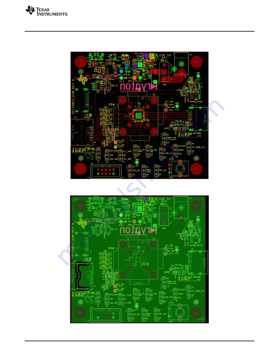
EVM Layout
Figure 14
through
Figure 19
illustrate the DP159RGZEVM PCB layouts.
Figure 14. Layer 1 (Top)
Figure 15. Layer 2 (GND)