


Hardware References
10
SPRUI76A – March 2017 – Revised January 2019
Copyright © 2017–2019, Texas Instruments Incorporated
Delfino™ TMS320F28379D controlCARD R1.3
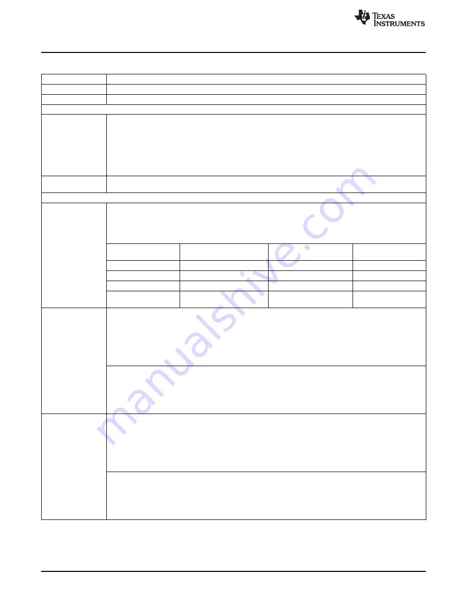
Table 2. Hardware References (continued)
A:D2
Turns on when ISO JTAG logic is powered on (green)
A:D3
JTAG/UART RX toggle indicator (blue)
A:D4
JTAG/UART TX toggle indicator (blue)
Resistors and Capacitors
R59, R60
Alternate Reference Configuration Resistors
These resistors allow the user to choose whether the alternate reference for the ADCs will be given by:
• If R59 is unpopulated & R60 is populated
A precision 3.0V reference (REF5030)
• If R59 is populated & R60 is unpopulated
The reference will be given by pin 45 of the HSEC controlCARD connector. This will presumably allow the
baseboard to provide the desired voltage reference.
R27-R50 and C18-
C41
Optional RC input filter for all ADC inputs
Switches (default position in BOLD)
SW1
Boot Mode Switch:
Controls the Boot Options of the F2837x device. For more information. (0 is down, 1 is up), see the device-specific
data sheet.
Mode # Switch Position 1 (GPIO-72) Switch Position 2 (GPIO-84) Boot from 00 0 0 Parallel I/O 01 0 1 Boot from
SCI 02 1 0 Wait Boot Mode 03 1 1 Get Mode (Flash by default)
Mode #
Switch Position 1
(GPIO-72)
Switch Position 2
(GPIO-84)
Boot from
00
0
0
Parallel I/O
01
0
1
Boot from SCI
02
1
0
Wait Boot Mode
03
1
1
Get Mode (Flash by
default)
SW2
ADC VREFHI Control Switch for ADC modules A & B:
Switch 1 (lower switch) – VREFHI Control Switch for ADC module A:
• In the left position – ADC-A is configured to use VDDA (3.3 V) as the ADC’s voltage reference. The full-scale
range of this ADC will be 0-3.3 V, but the ADC will have reduced accuracy/precision.
•
In the right position
– ADC-A is configured to either use a precise 3.0 V voltage reference or an external
voltage may be used as a reference. R59 and R60 determine which setting is used (see description for
R59/R60, above)
Switch 2 (upper switch) – VREFHI Control Switch for ADC module B:
• In the left position – ADC-B is configured to use VDDA (3.3 V) as the ADC’s voltage reference. The full-scale
range of this ADC will be 0-3.3 V, but the ADC will have reduced accuracy/precision.
•
In the right position
– ADC-B is configured to either use a precise 3.0 V voltage reference or an external
voltage may be used as a reference. R59 and R60 determine which setting is used (see description for
R59/R60, above)
SW3
ADC VREFHI Control Switch for ADC modules C & D:
Switch 1 (lower switch) – VREFHI Control Switch for ADC module C:
•
In the left position
– ADC-C is configured to use VDDA (3.3 V) as the ADC’s voltage reference. The full-scale
range of this ADC will be 0-3.3V, but the ADC will have reduced accuracy/precision.
•
In the right position
– ADC-C is configured to either use a precise 3.0 V voltage reference or an external
voltage may be used as a reference. R59 and R60 determine which setting is used (see description for
R59/R60, above)
Switch 2 (upper switch) – VREFHI Control Switch for ADC module D:
•
In the left position
– ADC-D is configured to use VDDA (3.3 V) as the ADC’s voltage reference. The full-scale
range of this ADC will be 0-3.3V, but the ADC will have reduced accuracy/precision.
•
In the right position
– ADC-D is configured to either use a precise 3.0 V voltage reference or an external
voltage may be used as a reference. R59 and R60 determine which setting is used (see description for
R59/R60, above).