background image

System Setup

www.ti.com

4

SLAU805 – July 2019

Submit Documentation Feedback

Copyright © 2019, Texas Instruments Incorporated

DAC53401EVM

2

System Setup

2.1

Software Setup

This section provides the procedure for EVM software installation.

2.1.1

Operating Systems

The EVM software is compatible with the Windows™ 7, 8, and 10 operating systems.

2.1.2

Software Installation

The software is available on the product folder, and can also be found in the

GUI Composer Gallery

.

Search for

DAC53401EVM

inn the GUI Composer Gallery. Use the down arrow symbol to download the

software. There are two downloads:

DAC53401EVM GUI

and

GUI Composer Runtime

. Either download

both, or just download the EVM GUI; the runtime can be downloaded through the EVM GUI during
installation. The software can also be run online by clicking; however, only after the firmware and driver
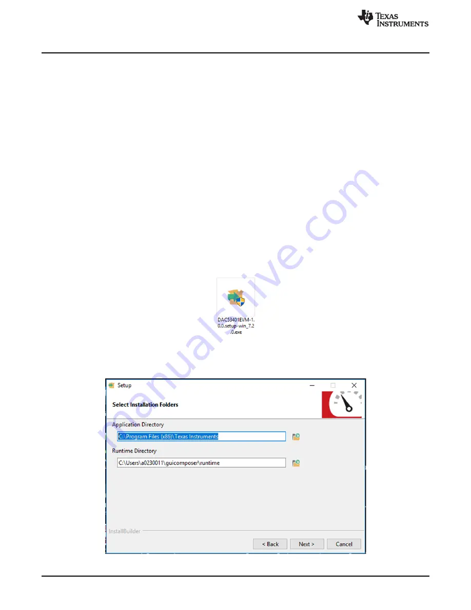
are upgraded. After the software is downloaded onto the PC, navigate to the download folder, and run the
DAC53401EVM software executable, as shown in

Figure 1

. When the DAC53401EVM software is

launched, an installation dialog window opens and prompts the user to select an installation directory. If
left unchanged, the software location defaults to

C:\Program Files (x86)\Texas Instruments\DAC53401

EVM

as shown in

Figure 2

If there is no previous installation of the

GUI Composer Runtime

application,

the installer also requests for an automatic download from the web. Select either

Install from Web

to

download and install from the web, or

Install from PC

and provide the path to the local file that is already

downloaded. The runtime also installs the USB drivers, unless the drivers are already installed.

Figure 1. DAC53401EVM Software Setup

The software installation automatically copies the required files and drivers to the local machine.

Figure 2. Software Installation Path

Summary of Contents for DAC43401

Page 1: ...is EVM is designed to evaluate the performance of the DAC53401 buffered voltage output DAC in a variety of configurations Throughout this document the terms evaluation board evaluation module and EVM...

Page 2: ...hematic Page 1 22 21 BOOSTXL DAC PORT Schematic Page 2 23 22 DAC53401EVM Schematic 24 23 BOOSTXL DAC PORT PCB Components Layout 25 24 BOOSTXL DAC PORT Top Layer 25 25 BOOSTXL DAC PORT Bottom Layer 26...

Page 3: ...rface using a PC based graphical user interface GUI 1 1 Kit Contents Table 1 details the contents of the EVM kit Contact the TI Product Information Center nearest you if any component is missing TI hi...

Page 4: ...r only after the firmware and driver are upgraded After the software is downloaded onto the PC navigate to the download folder and run the DAC53401EVM software executable as shown in Figure 1 When the...

Page 5: ...procedure below to upgrade the firmware and install the device drivers successfully 1 Remove jumper JP6 on the Analog EVM Controller as shown in step 1 of Figure 4 2 Mount jumper on 5V OTG Retain the...

Page 6: ...r external power supplies This platform is designed to host additional boards stacked up on the BOOSTXL DAC PORT in order to provide extended functions Figure 5 displays the system setup Figure 5 Hard...

Page 7: ...Section 2 2 1 the BOOSTXL DAC PORT and DAC53401EVM can be connected as shown in Figure 6 Connect the USB cable from the Analog EVM Controller OTG USB Port U7 to the PC Figure 6 Hardware Setup Guideli...

Page 8: ...EVM hardware and jumper configuration settings 3 1 1 Theory of Operation for the BOOSTXL DAC PORT The BOOSTXL DAC PORT is a generic evaluation platform for catalog DACs that provides various options f...

Page 9: ...C External LDAC I O 36 EXT_LDAC External LDAC I O 37 SPI_BUF_EN Digital SPI buffer enable 38 GPIO General purpose I O 39 GPIO General purpose I O 40 GPIO General purpose I O Table 7 BOOSTXL DAC PORT J...

Page 10: ...nput 14 GND Ground 15 VCC VCC output 16 VDD VDD output Table 9 BOOSTXL DAC PORT J5 Pin Definitions Pin Signal Description 1 AIO1 Analog I O 2 AGND Analog Ground 3 AIO3 Analog I O 4 AIO5 Analog I O 5 A...

Page 11: ...cumentation Feedback Copyright 2019 Texas Instruments Incorporated DAC53401EVM 3 1 3 Theory of Operation for the DAC53401EVM Hardware The block diagram of the DAC53401EVM board is displayed in Figure...

Page 12: ...ce input 6 NC Not connected 7 NC Not connected 8 NC Not connected 9 NC Not connected 10 NC Not connected 11 NC Not connected 12 NC Not connected 13 AGND Analog ground 14 AGND Analog ground 15 AGND Ana...

Page 13: ...Programs menu and select the DAC53401 EVM icon Figure 9 DAC53401EVM GUI Location Figure 10 shows that if the Analog EVM Connector is connected correctly the status bar at the bottom of the screen dis...

Page 14: ...help configure the DAC53401 device These functions are built into several GUI pages as shown in the following sections The Menu allows the user to switch between the pages with each page representing...

Page 15: ...DAC53401EVM 3 2 2 2 Setup Page This page shown in Figure 12 guides the user to perform a one time firmware upgrade for the Analog EVM Controller and details how the Analog EVM Controller BOOSTXL DAC...

Page 16: ...nce and output span and program the output voltage decimal for the DAC53401 The DAC53401 comes in Hi Z power down mode by default NOTE The basic DAC setup for power up reference selection and output s...

Page 17: ...s page provides the settings for margin low margin high and nominal DAC outputs along with code step and slew rate for the ramp generation The margin low and the margin high triggers are by the respec...

Page 18: ...most basic setting for this functionality is the function selection triangular wave saw tooth wave reverse saw tooth wave and square wave The margin low and margin high settings define the lower and...

Page 19: ...e margin low and margin high In addition to these settings the medical alarms have three more settings interburst time pulse off time and pulse on time These settings have four common settings that ta...

Page 20: ...me configuration lists and action buttons provided on the Register Map page The values of the register map can be stored locally by pressing the Save Registers button under the File menu option Additi...

Page 21: ...05 July 2019 Submit Documentation Feedback Copyright 2019 Texas Instruments Incorporated DAC53401EVM 3 2 2 5 Collateral Page This page shown inFigure 19 provides links for all the collateral on the DA...

Page 22: ...ubmit Documentation Feedback Copyright 2019 Texas Instruments Incorporated DAC53401EVM 4 Schematic PCB Layout and Bill of Materials This section contains the complete bill of materials and schematic d...

Page 23: ...uments Incorporated www ti com Schematic PCB Layout and Bill of Materials 23 SLAU805 July 2019 Submit Documentation Feedback Copyright 2019 Texas Instruments Incorporated DAC53401EVM Figure 21 BOOSTXL...

Page 24: ...PCB Layout and Bill of Materials www ti com 24 SLAU805 July 2019 Submit Documentation Feedback Copyright 2019 Texas Instruments Incorporated DAC53401EVM 4 2 DAC53401EVM Schematic Figure 22 DAC53401EVM...

Page 25: ...Documentation Feedback Copyright 2019 Texas Instruments Incorporated DAC53401EVM 4 3 PCB Components Layout Figure 23 through Figure 27 show the layout of the components for the DAC53401EVM board Figu...

Page 26: ...d Bill of Materials www ti com 26 SLAU805 July 2019 Submit Documentation Feedback Copyright 2019 Texas Instruments Incorporated DAC53401EVM Figure 25 BOOSTXL DAC PORT Bottom Layer Figure 26 DAC53401EV...

Page 27: ...www ti com Schematic PCB Layout and Bill of Materials 27 SLAU805 July 2019 Submit Documentation Feedback Copyright 2019 Texas Instruments Incorporated DAC53401EVM Figure 27 DAC53401EVM Layers...

Page 28: ...cle 2 54mm 16x1 TH PPTC161LFBN RC Sullins Connector Solutions J3 J6 J7 J8 J9 J10 6 Header 2 54mm 3x1 Gold SMT Header 2 54mm 3x1 SMT TSM 103 01 L SV P TR Samtec J4 J5 2 Header 2 54mm 16x1 TH Header 2 5...

Page 29: ...Compact Testpoint 5005 Keystone TP5 1 Test Point Miniature SMT Test Point Miniature SMT 5019 Keystone U1 1 4 Bit Bidirectional Multi Voltage Level Translator for Open Drain Push Pull PW0014A TSSOP 14...

Page 30: ...2 54mm 16x1 TH Header 2 54mm 16x1 TH 22284160 Molex R3 R6 R7 R8 R15 R16 R17 R18 9 10 0k RES 10 0 k 1 0 1 W 0603 0603 RC0603FR 0710KL Yageo America U1 1 10 Bit I2C Interface Buffered Voltage Output DA...

Page 31: ...e resources are subject to change without notice TI grants you permission to use these resources only for development of an application that uses the TI products described in the resource Other reprod...

Reviews: