Texas Instruments DAC3482 User Manual Download Page 11

www.ti.com

Basic Test Procedure

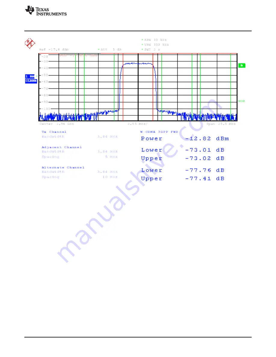
(Baseband = 30MHz, NCO = 30MHz with NCO Gain disabled, QMC Gain = 1446, LO = 1900MHz)

Figure 9. D TRF3703-15 WCDMA Output

11

SLAU336 – March 2011

DAC3484/DAC3482 EVM

Submit Documentation Feedback

© 2011, Texas Instruments Incorporated

Summary of Contents for DAC3482

Page 1: ...EVM Block Diagram 2 2 Input Control Options 3 3 PLL Configuration 4 4 Digital Block Options 5 5 Output Control Options 6 6 CDCE62005 Tab Configured for 4x Interpolation 7 7 Test Set up Block Diagram...

Page 2: ...ic user s guide for the DAC3484 2 EVM Revision D The EVM provides a basic platform to evaluate the DAC3484 and DAC3482 which are a family of 1 25GSPS up to 16x interpolation 16 bit high speed digital...

Page 3: ...If needed you can access the drivers directly in the install directory 2 2 Software Operation The software allows programming control of the DAC device and the CDC device The front panel provides a ta...

Page 4: ...old time of DAC348x data latching Set the on chip LVDS DATACLOCK delay Typical setting of 160ps or more will help meet the timing requirement for most of the TSW3100 DAC348x EVM setup This LVDS DATACL...

Page 5: ...nchronization procedure Group Delay allows adjustment of group delay for each I Q channel This is useful for wideband sideband suppression Offset Adjustment allows adjustment of DC offset to minimize...

Page 6: ...Options Output Options allows the configuration of reference output polarity and output delay Data Routing provides flexible routing of the A B C and D digital path to the desired output channels Note...

Page 7: ...O The whole OSTR clock equation needs to take account of both the Y1 CDCE62005 clock divider ratio and the additional CDCP1803 divide by 2 clock divider O This OSTR signal can be a slower periodic si...

Page 8: ...e desired register file O Click on Send All to ensure all of the values are loaded properly Save Regs Saves the register configuration for all devices 2 2 6 Miscellaneous Settings Reset USB Toggle thi...

Page 9: ...ut port of J23 to the spectrum analyzer DAC3484 2 EVM jumpers make sure the following jumpers are at their default setting 1 JP6 on pin 1 2 2 JP4 on pin 2 3 3 JP5 on pin 1 2 4 JP2 on pin 1 2 5 JP3 on...

Page 10: ...n in GUI and verify USB communication Switch to the INPUT tab of GUI Click LOAD REGS browse to the installation folder and load example file DAC3484_FDAC_1228p8MHz_4xint_NCO_30MHz_QMCon txt This file...

Page 11: ...dure Baseband 30MHz NCO 30MHz with NCO Gain disabled QMC Gain 1446 LO 1900MHz Figure 9 DAC3484 TRF3703 15 WCDMA Output 11 SLAU336 March 2011 DAC3484 DAC3482 EVM Submit Documentation Feedback 2011 Texa...

Page 12: ...ed Output Eight 0 Ohm resistors must be moved to configure the output of the DAC3484 to be 4 1 transformer coupled remove these resistors Horizontal position R19 R26 R33 R27 R35 R97 R76 R98 Install th...

Page 13: ...the installation folder and load example file DAC3484_FDAC_1228p8MHz_4xint_NCO_30MHz_QMCon txt This file contains settings for 4x interpolation with the DAC3484 running at 1228 8MSPS Load this file an...

Page 14: ...com baseband 30MHz NCO 30MHz with NCO Gain disabled QMC Gain 1446 Figure 12 DAC3484 Transformer Coupled Output at 60MHz IF 14 DAC3484 DAC3482 EVM SLAU336 March 2011 Submit Documentation Feedback 2011...

Page 15: ...e software can be configured as DAC3482 interface by selecting DAC3482 EVM Software Control from the upper left hand corner of the pull down menu The DAC3484 EVM needs to be configured differently for...

Page 16: ...is used as a Dual DAC Figure 15 shows a screen shot of TSW3100 GUI for generating a communication signal for DAC3482 LVDS output option is selected The setting displayed generates a single carrier WC...

Page 17: ...Optional Configuration Figure 15 TSW3100 GUI Configuration for Generating a WCDMA Signal for DAC3482 17 SLAU336 March 2011 DAC3484 DAC3482 EVM Submit Documentation Feedback 2011 Texas Instruments Inc...

Page 18: ...duct This notice contains important safety information about temperatures and voltages For additional information on TI s environmental and or safety programs please contact the TI application enginee...

Page 19: ...orized for use in safety critical applications such as life support where a failure of the TI product would reasonably be expected to cause severe personal injury or death unless officers of the parti...

Reviews: