


SWRU253A
October 2013
CC2533EMK Quick Start Guide
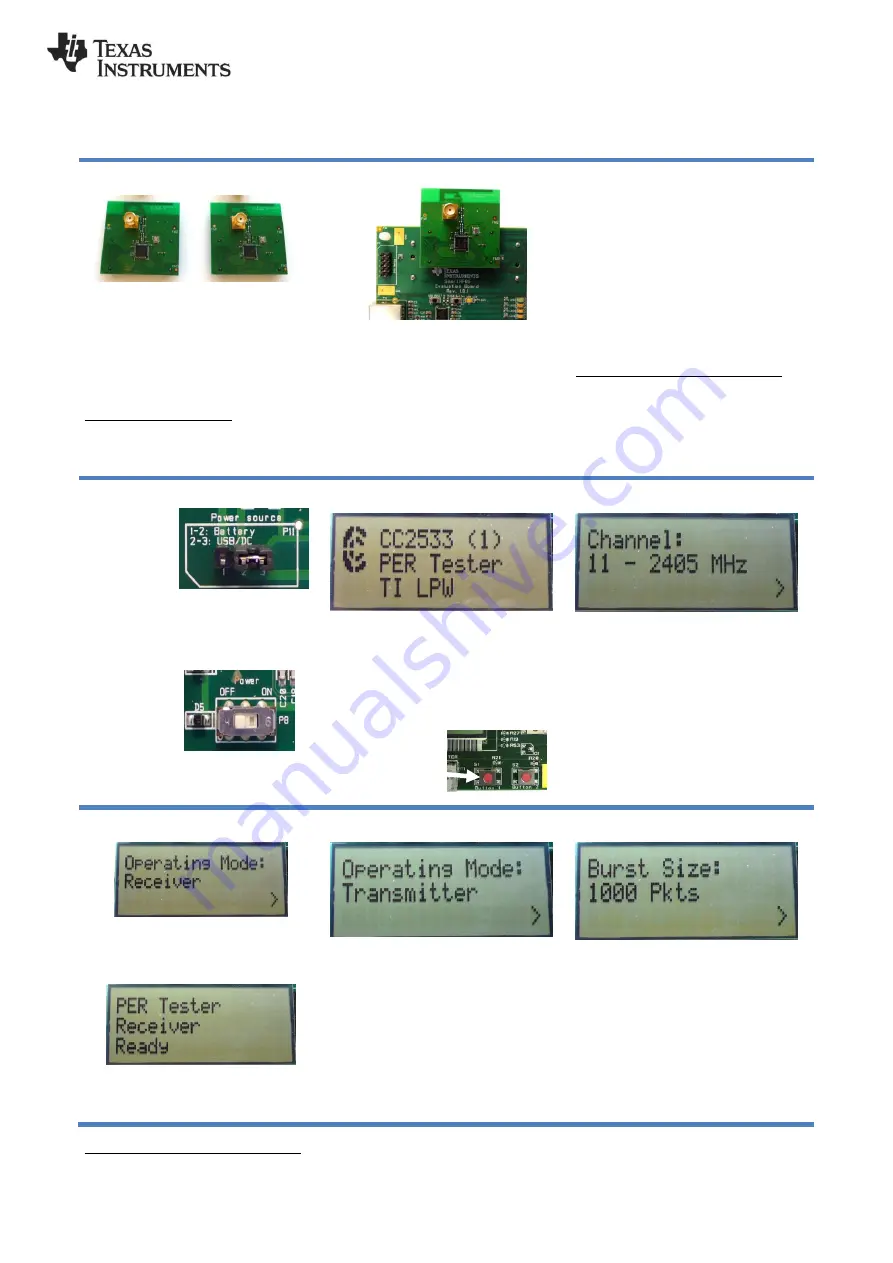
1. Kit Contents
2 x CC2533EM with PCB antennas
2 x Pulse W1010 2.4 GHz antennas
Documentation
The RF boards in this kit are FCC and IC certified
and tested to comply with ETSI/R&TTE standards
over temperature from 0 to +35°C. The antenna,
W1010 from Pulse, is a ¼ wave dipole antenna
with 2 dBi gain.
FCC/IC Regulatory Compliance
FCC Part 15 Class A Compliant
IC ICES-003 Class A Compliant
2. Plug EM into SmartRF05EB
In order to run the pre-programmed packet
error rate test on the device, you need 2
SmartRF05
Evaluation
Boards.
The
SmartRF05EB is included in the CC2533
Development Kit
Error! Reference source
not found.
.
Note that you DO NOT need the SMA
antenna, as the PCB antenna is used by
default.
3. Power Options
There are several ways of applying power
to the SmartRF05EB;
USB (5V through USB plug)
External Power Supply
(requirements below)
2 x 1.5V AA Non-Rechargeable Alkaline
Batteries
Voltage regulators on the SmartRF05EB
will set the on-board voltage to 3.3V.
External Power Supply
1
Requirements:
Nom Voltage: 4 to 20 VDC
Max Current: 1500 mA
Efficiency Level V
Warning!
To minimize risk of personal
injury or property damage, never use
rechargeable batteries to power the board.
4. Select Power Source
Locate
the
power source
header
P11
just above the
LCD on the
SmartRF05EB
Connect pins 1 and 2 if you are using
batteries to power the board. Connect pins
2 and 3 if you are using USB or external
power supply.
Once you have
set P11, find
switch P8 just
next to the DC
jack
on
the
SmartRF05EB.
To power on
the board, flip the switch fro
m “OFF” to
“ON”.
4. Packet Error Rate (PER)
When
power
is
applied
to
the
SmartRF05EB, the preprogrammed PER
test on the CC2533 will start running.
The LCD will display the screen as shown
in the picture above. The number in the
parentheses is the revision of the CC2533.
Press Button 1 to
continue.
5. Select Channel
Select one of the 16 IEEE 802.15.4
channels, with channel number from 11 to
26 (2405-2480 MHz, 5 MHz channel
spacing). Select the same channel for both
boards.
The channel number is increased by
moving the joystick in any direction.
Press Button 1 to confirm the selection.
6 Set up the Receiver
Set one of the boards to operate as
receiver. Use the joystick to select mode.
Confirm by pressing Button 1.
The receiver will now wait for packets from
the transmitter.
7. Set up the Transmitter
Set the other board to operate as
transmitter. Use the joystick to select mode.
Confirm the selection by pressing Button 1.
On
the
transmitter
node,
additional
parameters have to be set. On the next
screen, select the TX output power (signal
strength). Use the joystick to select
between -3 dBm, 0 dBm, 4.5 dBm or 7
dBm. Confirm the selection with Button 1.
8. TX: Packets and Packet Rate
Next, select burst size (number of packets
to send) by using the joystick, either 1000,
10K, 100K or 1M packets. Confirm the
selection with Button 1.
After selecting burst size, select packet
rate; 100, 50, 20 or 10 packet per second.
Confirm the selection with Button 1.
1
When using an external power supply, make sure it meets the listed requirements in addition to complying with applicable regional
product regulatory and safety certification requirements such as UL, CSA, VDE, CCC, and PSE.


