


SWRU285
June 2013
Web sites:
www.ti.com/lprf
E2E Forum:
www.ti.com/lprf-forum
Make sure to subscribe to the Low-Power RF
Newsletter to receive information about updates
to documentation, new product releases and
more. Sign up on the TI web pages.
CC1110EMK Quick Start Guide
Opening the box an running the Packet Error Rate Test on SmartRF04EB
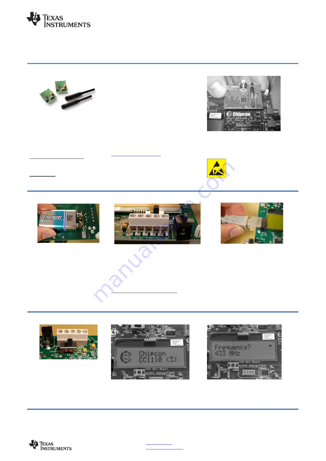
1. Kit Contents
2 x CC1110EM (433 MHz or 868-915 MHz)
2 x Antennas (type depending on frequency)
The 868-915 MHz RF boards in this kit are
FCC and IC certified and are tested to
comply with ETSI/R&TTE over temperatures
from 0 to +35°C.
FCC/IC Regulatory Compliance
FCC Part 15 Class A Compliant
IC ICES-003 Class A Compliant
Antenna types:
868-915 MHz: Pulse W5017, 2 dBi
433 MHz:
Pulse SPWH24433TI, 0 dBi
2. How to use the modules
The EMK is an add-on kit to supplement the
CC1110DK with evaluation boards supporting
additional frequency bands.
The CC1110EM boards can be plugged into several
development boards from Texas Instruments. Most
notably, you can use the SmartRF04EB, which is
included in the CC1110-CC1111DK. This board lets
you run a packet error rate (PER) test, control the
device from SmartRF™ Studio and it can be used as
a development platform.
It is also possible to plug the EM into the “SoC
Battery B
oard”. This board, together with the CC
Debugger, will provide a complete development
environment for the CC1110. See:
This guide will show how to use the modules together
with SmartRF04EB.
3. Plug EM into EB
Insert a CC1110EM into both SmartRF04EBs. The
connectors will only fit in one position, so that the
EM cannot be inserted the wrong way. Do not force
the EM. Remember to connect the antenna as well.
Caution!
The kit contains ESD sensitive
components. Handle with care to prevent
permanent damage. To minimize risk of
injury, avoid touching components during
operation if symbolized as hot.
4a. Battery power
There are three different ways of applying
power to the EB:
The first method involves using a battery,
either a 9V or a 4xAA battery pack
connected to the battery connector on the
bottom side of the board
Warning!
To minimize risk of personal injury
or property damage, never use rechargeable
batteries to power the board.
4b. DC power
The second method applies DC power using the
DC input jack (right in picture, centre is +, sleeve is
ground), or by connecting a 4-10V voltage source
between the 4-10V and 0V terminals of the power
connector (left in picture). It is also possible to
connect a 3.3V voltage source between the 3.3V
and 0V terminals. The on-board voltage regulators
will be bypassed in this case.
External Power Supply
i
Requirements:
Nom Voltage: 6 VDC
Max Current: 800 mA
Efficiency Level V
4c. USB power
The EB can also be powered from the USB bus.
Make sure that the SmartRF
™ Studio software is
installed before connecting the EB to the PC;
otherwise you may experience problems in
installing it later due to driver issues.
Note that if multiple power sources are connected,
the source with the highest voltage will power the
EB.
This means that you should disconnect any
attached battery when using a lab supply or
USB power; otherwise the battery will be
drained.
5. Set power switch
If a 3.3V source is used as described in 4b
above, the switch should be set to the
leftmost position. For all other cases, the
switch should be set to the rightmost
position. This switch can be used to turn off
the EB by switching it to the opposite
position of that used to turn it on
Do not leave the board powered when
unattended.
6. Packet error rate test
When power is applied to the board, the test
program will start. You should see the Chipcon logo
with chip name and revision number as shown
above on the LCD display on both EBs. Pushing
button S1 in the lower right corner of the board will
show the first menu item.
7. Select Frequency
Select the frequency that you want to use (433
MHz, 868 MHz, 903 MHz or 915 MHz). Move the
joystick up or down to display the choices and push
button S1 in the lower right corner of the board to
select the displayed frequency.