


bq769x0 Circuit Module Use
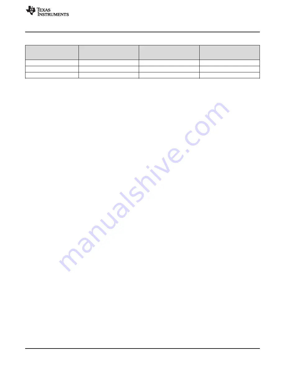
Table 3. Reducing Cell Count (continued)
Unused Cell (Numbered
Input and Balance FET Gate
from Bottom, Bottom = Cell
Short Cell Terminals
Short AFE Inputs
Resistors to Remove
1)
Cell 8
C8 to C7
R24, R34
VC8 to VC7
Cell 4
C4 to C3
R28, R38
VC4 to VC3
Cell 3
C3 to C2
R29, R39
VC3 to VC2
When evaluating the gauge, it is recommended to reduce the cell count of the gauge configuration before
connecting the cells. If the gauge does not see voltage it will shut down the AFE and require re-boot of the
board. To avoid shutdown simulate a charge current until the cell count configuration can be corrected.
6.5
Connecting Cells
The EVM is constructed to sense the cell voltages at the cells. Separate wires are required from the
bottom of the battery stack to the C0 connection at the terminal block for sensing voltage and from the
bottom of the battery stack to the BATT- terminal to carry the load current. The AFE IC VSS is referenced
to the BATT- connection. Similarly, separate wires are required from the top of the battery stack to the top
cell input of the terminal block and from the top of the battery stack to the BATT+ terminal to carry the
load current. The top cell sense connection also powers the AFE IC. To move the top sense connection
from the cells to the board, R51 could be populated on the bq76940EVM, or R50 could be populated on
the bq76930EVM. To move the bottom cell sense to the cells, R1 could be populated, or leave the bottom
cell simulator switch section closed to connect C0 to BATT-.
The cell simulator provides resistors between the cell inputs. These resistors can help divide the voltage
as cells are connected. If desired, the cell simulator switches can be closed during cell connection and
opened after cell connection. The switches must be opened after connection of cells or the cells are
discharged by the constant drain of the cell simulator. If you see the orange LED on when cells are
connected, open the dip switch sections to remove the load.
Cell connection is generally considered safest from the bottom up. This minimizes the step size of the
voltage applied to the board. Recommended connection sequence for the EVM when connecting wires
individually is bottom up:
1. Connect BATT-
2. Connect cells bottom up, C0, C1, C2 ...
3. Connect BATT+
4. Open the cell simulator switches, if needed
When the top and bottom cells are connected on the board:
1. Connect BATT- (includes C0)
2. Connect cells bottom up; C1, C2, C3...
3. Connect BATT+ (includes top cell)
4. Open the cell simulator switches, if needed
When cells are mated with a connector or connectors such as on the EVM:
1. Connect BATT- or the node which connects VSS of the AFE, if separate
2. Mate the connector for the lower cells
3. Mate the connector for the upper cells, if separate
4. Connect the BATT+, if separate
5. Open the cell simulator switches, if needed
When using external balancing with P-channel MOSFETs, such as on the bq76930 and bq76940 EVMs,
the inrush current for a cell can momentarily turn on the balance FET causing the next cell input below to
rise. This can continue down the stack. Connecting C0 to BATT- on the board by closing the C0 cell
simulator dip switch during cell connection can reduce stress on the VC0 input of the AFE. The switch can
be opened after cell connection for sensing at the cell.
29
SLVU925B – April 2014 – Revised July 2014
bq76930 and bq76940 Evaluation Module User's Guide
Copyright © 2014, Texas Instruments Incorporated