Texas Instruments bq27531EVM User Manual Download Page 17

www.ti.com

Operation

17

SLUUA90A – April 2013 – Revised July 2016

Submit Documentation Feedback

Copyright © 2013–2016, Texas Instruments Incorporated

bq27531EVM With bq27531 Battery Management Unit Impedance Track™

Fuel Gauge and bq24192 4.5-A, Switch-Mode Battery Charger for Single-Cell

Applications

6

Operation

This section details the operation of the bqStudio software.

6.1

Starting the Program

Run bqStudio from the Start | All Programs | Texas Instruments | Battery Management Studio. The main
screen (

Figure 9

appears. If instead of

Figure 9

appearing,

Figure 10

appears, it may mean that the EVM

is not connected to the computer correctly. Make sure that the USB interface (EV2300 or EV2400 or GDK)
and the bq27531 are connected and restart bqStudio. If this still does not resolve the issue, check if the
I2C pullup resistors are connected. Data begins to appear once the <Refresh> (single-time scan) button is
clicked, or when the Scan button is clicked. To disable the scan feature, simply click the

Scan

button

again.

The continuous scanning period can be set by opening Window | Preferences

Registers section. The

range for this interval is 0 ms to 65,535 ms. Only items that are selected for scanning are scanned within
this period.

Battery Management Studio provides a logging function which logs the values that were last scanned. To
enable this function, select the Start Log button; this causes the Scan button to be pressed. When logging
is Stopped, the Scan button will still be selected and has to be manually clicked again.

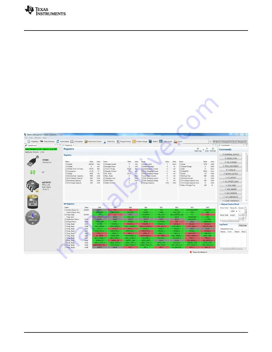
Figure 9. Registers Screen

This screen (

Figure 9

shows the RAM data in the bq27531 device. Additional Flags and Status data can

be viewed at the bottom of the

Registers

screen.

Summary of Contents for bq27531EVM

Page 1: ...system side fuel gauge solution as well as to charge the battery from either an adapter or USB input with up to 4 5 A of charge current The circuit module connects directly across the battery pack Wi...

Page 2: ...able in product folder on TI website Ability to upgrade to the latest firmware version by flash reprogramming 1 1 Kit Contents bq27531 G1 and bq24192 chipset circuit module PWR216 NTC103AT thermistor...

Page 3: ...ised July 2016 Submit Documentation Feedback Copyright 2013 2016 Texas Instruments Incorporated bq27531EVM With bq27531 Battery Management Unit Impedance Track Fuel Gauge and bq24192 4 5 A Switch Mode...

Page 4: ...Adapter negative terminal J4 SYS System positive terminal J5 SYS System positive terminal J5 GND System negative terminal J6 GND System negative terminal J7 TEST Test terminal J8 USB Miniconnector J9...

Page 5: ...r for USB data lines DM D and DP D When shorted USB input current limit defaults to 1 5 A Otherwise USB100 mode is selected INSTALLED JP2 PSEL 2 3 PSEL LO Indicates that an ac adapter is connected to...

Page 6: ...Track Fuel Gauge and bq24192 4 5 A Switch Mode Battery Charger for Single Cell Applications 3 Circuit Module Physical Layouts Bill of Materials and Schematic This section contains the board layout bil...

Page 7: ...A90A April 2013 Revised July 2016 Submit Documentation Feedback Copyright 2013 2016 Texas Instruments Incorporated bq27531EVM With bq27531 Battery Management Unit Impedance Track Fuel Gauge and bq2419...

Page 8: ...A90A April 2013 Revised July 2016 Submit Documentation Feedback Copyright 2013 2016 Texas Instruments Incorporated bq27531EVM With bq27531 Battery Management Unit Impedance Track Fuel Gauge and bq2419...

Page 9: ...A90A April 2013 Revised July 2016 Submit Documentation Feedback Copyright 2013 2016 Texas Instruments Incorporated bq27531EVM With bq27531 Battery Management Unit Impedance Track Fuel Gauge and bq2419...

Page 10: ...A90A April 2013 Revised July 2016 Submit Documentation Feedback Copyright 2013 2016 Texas Instruments Incorporated bq27531EVM With bq27531 Battery Management Unit Impedance Track Fuel Gauge and bq2419...

Page 11: ...ctor Male Straight 2x5 pin 100mil spacing 4 Wall 0 338 x 0 788 inch N2510 6002 RB 3M 1 J8 UX60 MB 5ST Connector Recpt USB B Mini 5 pins SMT 0 354 X 0 303 Inches UX60 MB 5ST Hirose Electric Co 2 D1 D2...

Page 12: ...2 J5 J7 J13 ED555 2DS Terminal Block 2 pin 6 A 3 5mm 0 27 x 0 25 ED555 2DS OST 1 J12 ED555 3DS Terminal Block 3 pin 6 A 3 5mm 0 41 x 0 25 inch ED555 3DS OST 0 TP1 TP2 TP3 TP4 TP5 TP6 TP7 TP8 TP9 TP10...

Page 13: ...sters set via bq27531 software 3 4 2 4 44 V Supply current IIN MAX Maximum input current from ac adapter input registers set via bq27531 software 1 5 3 A Fast charge current ICHRG MAX Battery charge c...

Page 14: ...ions use short twisted pair wires of appropriate gauge wire for the amount of the current 2 Set Power Supply 1 PS 1 for 6 V 3 A current limit and then turn off supply 3 If BAT_Load as shown in Figure...

Page 15: ...ware The main window of the software is shown in Figure 9 DataRAM Screen 4 2 Software Installation Find the latest software version at http www ti com tool bqStudio Use the following steps to install...

Page 16: ...to the PC through a USB cable before starting this procedure 2 Browse for the supported software link within the bq27531 TI web site product folder to find the downloadable EVSW installation files 3 O...

Page 17: ...this still does not resolve the issue check if the I2C pullup resistors are connected Data begins to appear once the Refresh single time scan button is clicked or when the Scan button is clicked To d...

Page 18: ...cations Figure 10 bqStudio Default Page 6 2 Setting Programmable bq27531 Options The bq27531 data memory comes configured per the default settings detailed in the bq27531 technical reference manual SL...

Page 19: ...d entering a file name The configuration is saved to a gg csv file The module calibration data is also held in the bq27531 data memory If the Gauge Dashboard is not displaying any information then the...

Page 20: ...as indicated below button 7 4 Board Offset Calibration This performs the offset calibration for the current offset of the board It takes approximately 35 seconds to complete It is expected that no cu...

Page 21: ...nit Impedance Track Fuel Gauge and bq24192 4 5 A Switch Mode Battery Charger for Single Cell Applications 8 Advanced Communication I2 C 8 1 I 2 C Communication I2 C read write operations are not speci...

Page 22: ...documents also can be obtained through the TI Web site at www ti com bq27531 System Side Impedance Track Fuel Gauge With Integrated LDO data sheet SLUSBE7 Revision History NOTE Page numbers for previ...

Page 23: ...ing the warranty period to the address designated by TI and that are determined by TI not to conform to such warranty If TI elects to repair or replace such EVM TI shall have a reasonable time to repa...

Page 24: ...transmitter has been approved by Industry Canada to operate with the antenna types listed in the user guide with the maximum permissible gain and required antenna impedance for each antenna type indic...

Page 25: ...ified allowable ranges some circuit components may have elevated case temperatures These components include but are not limited to linear regulators switching transistors pass transistors current sens...

Page 26: ...REMOVAL OR REINSTALLATION ANCILLARY COSTS TO THE PROCUREMENT OF SUBSTITUTE GOODS OR SERVICES RETESTING OUTSIDE COMPUTER TIME LABOR COSTS LOSS OF GOODWILL LOSS OF PROFITS LOSS OF SAVINGS LOSS OF USE L...

Page 27: ...sponsible for compliance with all legal regulatory and safety related requirements concerning its products and any use of TI components in its applications notwithstanding any applications related inf...

Reviews: