Texas Instruments BQ2515 EVM Series User Manual Download Page 8

Board Layouts, Schematics, and Bill of Materials

www.ti.com

8

SLUUBV0A – July 2018 – Revised August 2019

Submit Documentation Feedback

Copyright © 2018–2019, Texas Instruments Incorporated

BQ2515xEVM Evaluation Module

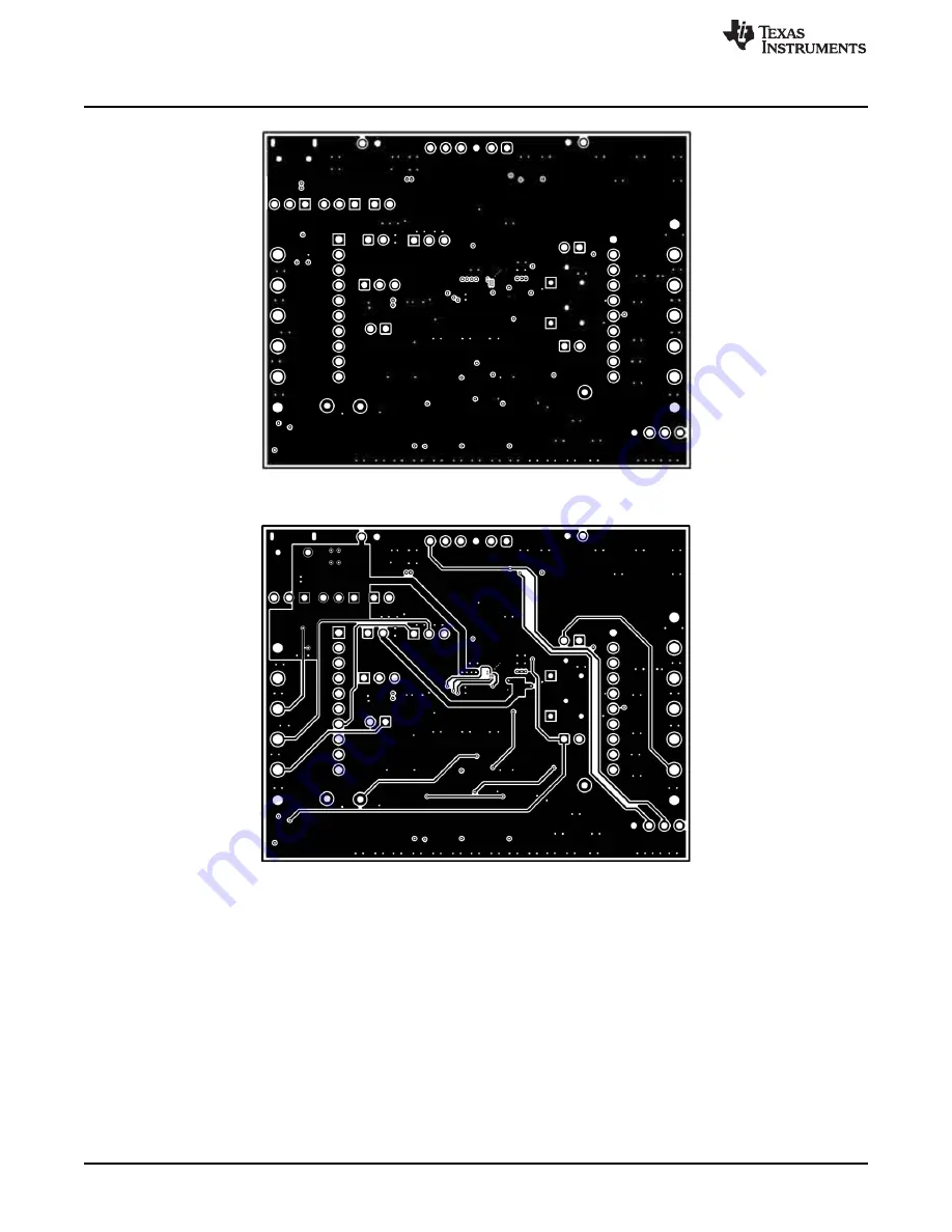
Figure 6. Signal Layer 1

Figure 7. Signal Layer 2

Summary of Contents for BQ2515 EVM Series

Page 1: ...ation module unless otherwise noted Contents 1 Introduction 2 1 1 EVM Features 2 1 2 I O Descriptions 2 2 Test Summary 4 2 1 Equipment 4 2 2 Charge Mode 5 2 3 Ship Mode 6 2 4 Warning 6 2 5 Comparison...

Page 2: ...urable Termination Current down to 0 5mA Programmable thermal charging profile with configurable Hot Warm Cool and Cold thresholds Power Path Management for powering the system and charging the batter...

Page 3: ...IO Connect CE to VIO J14 Display connector for other modules NA J15 PMID to VINLS connector Connected J16 On board LED pullup to VDD or PMID Connected to PMID J17 I2C Pullup Connected Table 3 lists th...

Page 4: ...perform tests on this EVM 1 Powersupply PS 1 Powersupply PS 2 Keithley 2400 Powersupply or equivalent 2 SC 1 SC 3 4 channel Oscilloscope 3 Computer A computer with at least one USB port and a USB cabl...

Page 5: ...1 The VPMID will rise to the level of VIN The device will begin to charge as long as CE pin jumper is disconnected J13 being pulled off will result in the pulldown internal to the device charge enable...

Page 6: ...p Mode as the voltage on PMID SC 2 will fall to 0V Figure 3 BQStudio Software Tool 2 4 Warning The warning label indicates when there is a fault during communication with the MCU 2 5 Comparison Table...

Page 7: ...d August 2019 Submit Documentation Feedback Copyright 2018 2019 Texas Instruments Incorporated BQ2515xEVM Evaluation Module 3 Board Layouts Schematics and Bill of Materials 3 1 Board Layouts Figure 4...

Page 8: ...Bill of Materials www ti com 8 SLUUBV0A July 2018 Revised August 2019 Submit Documentation Feedback Copyright 2018 2019 Texas Instruments Incorporated BQ2515xEVM Evaluation Module Figure 6 Signal Lay...

Page 9: ...hematics and Bill of Materials 9 SLUUBV0A July 2018 Revised August 2019 Submit Documentation Feedback Copyright 2018 2019 Texas Instruments Incorporated BQ2515xEVM Evaluation Module Figure 8 Bottom La...

Page 10: ...l of Materials www ti com 10 SLUUBV0A July 2018 Revised August 2019 Submit Documentation Feedback Copyright 2018 2019 Texas Instruments Incorporated BQ2515xEVM Evaluation Module Figure 10 Top Solder M...

Page 11: ...atics and Bill of Materials 11 SLUUBV0A July 2018 Revised August 2019 Submit Documentation Feedback Copyright 2018 2019 Texas Instruments Incorporated BQ2515xEVM Evaluation Module Figure 12 Drill Draw...

Page 12: ...DNP TS 14 3k R5 DNP VDD PG 14 3k R6 DNP IN A1 PMID A2 BAT A3 GND A4 PG B1 PMID B2 BAT B3 TS B4 CE C2 MR C1 IMAX C3 ADCIN C4 VDD D1 INT D2 LP D3 LDO D4 VIO E1 SDA E2 SCL E3 VINLS E4 BQ25150YFPR U1 0 1u...

Page 13: ...1 GND EV2400 I2C Jumper Connections LEDs 3p3V VINLS 1 2 J15 PMID CE J1 7 J1 8 1 2 D2 LTST C190CKT 1 2 D3 LTST C190CKT 499 R11 499 R12 GND J2 8 J2 9 1 2 J6 VIN GND TP16 TP15 SCL SDA TP14 3p3V 1 2 3 J13...

Page 14: ...witch_PushButton 2 1 SW3 Switch_PushButton SW3 SW2 SW1 User Menu Switches Board Layouts Schematics and Bill of Materials www ti com 14 SLUUBV0A July 2018 Revised August 2019 Submit Documentation Feedb...

Page 15: ...RM155R71E104KE14D MuRata C6 BQ25150EVM 1 4 7uF CAP CERM 4 7 F 10 V 20 X5R 0402 0402 GRM155R61A475MEAAD MuRata C6 BQ25155EVM 1 10uF CAP CERM 10 F 10 V 20 X5R 0402 0402 0402ZD106MAT2A AVX D1 D2 D3 D4 4...

Page 16: ...t 100mil Gold plated Black Shunt SNT 100 BK G Samtec 969102 0000 DA 3M TP1 TP2 TP4 TP5 TP7 TP14 6 Test Point Multipurpose Orange TH Orange Multipurpose Testpoint 5013 Keystone TP3 TP6 TP8 TP12 4 Test...

Page 17: ...17 SLUUBV0A July 2018 Revised August 2019 Submit Documentation Feedback BQ2515xEVM Evaluation Module...

Page 18: ...ring your application meets applicable standards and any other safety security or other requirements These resources are subject to change without notice TI grants you permission to use these resource...

Page 19: ...ther than TI b the nonconformity resulted from User s design specifications or instructions for such EVMs or improper system design or c User has not paid on time Testing and other quality control tec...

Page 20: ...These limits are designed to provide reasonable protection against harmful interference in a residential installation This equipment generates uses and can radiate radio frequency energy and if not in...

Page 21: ...instructions set forth by Radio Law of Japan which includes but is not limited to the instructions below with respect to EVMs which for the avoidance of doubt are stated strictly for convenience and s...

Page 22: ...any interfaces electronic and or mechanical between the EVM and any human body are designed with suitable isolation and means to safely limit accessible leakage currents to minimize the risk of electr...

Page 23: ...R DAMAGES ARE CLAIMED THE EXISTENCE OF MORE THAN ONE CLAIM SHALL NOT ENLARGE OR EXTEND THIS LIMIT 9 Return Policy Except as otherwise provided TI does not offer any refunds returns or exchanges Furthe...

Page 24: ...e resources are subject to change without notice TI grants you permission to use these resources only for development of an application that uses the TI products described in the resource Other reprod...

Page 25: ...Mouser Electronics Authorized Distributor Click to View Pricing Inventory Delivery Lifecycle Information Texas Instruments BQ25155EVM...

Reviews: